
EMO OBD tool

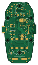
About the EMO OBD tool PCB
EMO OBD tool is an open source PIC PCB design by darshanram008, published on GitHub under the Custom license license. It is a 2-layer board measuring 35.1 × 62.7 mm, with 102 components from 65 distinct parts.
Its main chip is the PIC18F27Q84-E/SO, from the PIC family. Other key parts include the MCP2551-I/SN, 634-CP2102-GMR and AT24C256C-SSHL-T. By type, the board carries 42 resistors, 31 test points, 14 capacitors, 4 ICs, 4 connectors and 4 diodes.
It belongs with the power & battery designs in this gallery.
From the project
On board diagnostic tool for Battery management system
Main components on the EMO OBD tool
EMO OBD tool bill of materials (BOM)
102 components, 65 distinct parts — part numbers from the project's BOM.
| Qty | Part | Footprint | Refs |
|---|---|---|---|
| 1 | PIC18F27Q84-E/SO PIC18F27Q84 Microchip Technology | PIC18F27Q84_SOIC127P1030X265-28N | U1 |
| 1 | MCP2551-I/SN MCP2551-I-P Microchip Technology | SOIC127P600X175-8N | U2 |
| 1 | 634-CP2102-GMR CP2102-GMR | QFN50P500X500X100-29N-D | U3 |
| 1 | AT24C256C-SSHL-T | AT24C256_SOIC127P600X175-8N | U4 |
| 1 | ABM7-10.000MHZ-D2Y-T 10MHz ABRACON | ABLS8000MHZB4T | Y2 |
| 1 | SAMTEC_03X02 samtec_03x02 | SAMTEC_1.27mm_03x02 | J1 |
| 1 | 240-004 I2C Digilent | PinHeader_1x04_P1.27mm_Vertical | J2 |
| 1 | USB4105-GF-A USB C 2.0 GCT | USB_C_Receptacle_HRO_TYPE-C-31-M-12 | J4 |
| 1 | SM03B-GHS-TB CAN | JST_GH_SM03B-GHS-TB_1x03-1MP_P1.25mm_Horizontal | J6 |
| 1 | JUMPER_2_OPEN Jumper_2_Open | SolderJumper-2_P1.3mm_Open_RoundedPad1.0x1.5mm | JP1 |
| 1 | SBU2 | testpoint_0.5mm | SBU2 |
| 1 | RA0 | testpoint_0.5mm | TP1 |
| 1 | RA1 | testpoint_0.5mm | TP2 |
| 1 | RA2 | testpoint_0.5mm | TP3 |
| 1 | RA3 | testpoint_0.5mm | TP4 |
| 1 | RA4 | testpoint_0.5mm | TP5 |
| 1 | D- | testpoint_0.5mm | TP7 |
| 1 | RC1 | testpoint_0.5mm | TP8 |
| 1 | RC2 | testpoint_0.5mm | TP9 |
| 1 | RB5 | testpoint_0.5mm | TP10 |
Show 45 more
| Qty | Part | Footprint | Refs |
|---|---|---|---|
| 1 | 5V | testpoint_0.5mm | TP11 |
| 1 | RB4 | testpoint_0.5mm | TP12 |
| 1 | ICSPLK | testpoint_0.5mm | TP15 |
| 1 | ICSDAT | testpoint_0.5mm | TP16 |
| 1 | SDA | testpoint_0.5mm | TP17 |
| 1 | SCL | testpoint_0.5mm | TP18 |
| 1 | SBU1 | testpoint_0.5mm | TP19 |
| 2 | GND | testpoint_0.5mm | TP20, TP33 |
| 1 | CH | testpoint_0.5mm | TP21 |
| 1 | CL | testpoint_0.5mm | TP22 |
| 1 | CAN_TX | testpoint_0.5mm | TP23 |
| 1 | CAN_RX | testpoint_0.5mm | TP24 |
| 1 | 5V_PIC | testpoint_0.5mm | TP25 |
| 1 | cout | testpoint_0.5mm | TP26 |
| 1 | cin | testpoint_0.5mm | TP27 |
| 1 | 5V_MCP | testpoint_0.5mm | TP29 |
| 1 | Vref | testpoint_0.5mm | TP30 |
| 1 | RCO | testpoint_0.5mm | TP31 |
| 1 | D+ | testpoint_0.5mm | TP32 |
| 1 | TX | testpoint_0.5mm | TP38 |
| 1 | RX | testpoint_0.5mm | TP39 |
| 1 | SP0505BAHTG SP0505BAHT | SP0505BAHT_SOT95P280X145-6N.kicad_mod | D1 |
| 2 | LED bivar | LED_D3.0mm_IRBlack | D2, D4 |
| 1 | LED bivar | LED_0603_1608Metric | D3 |
| 4 | CC0402MRX5R7BB475 4.7uF/25V YAGEO | C_0402_1005Metric | C1, C2, C9, C12 |
| 1 | MPN: CC0402MRX5R7BB475 4.7uF/25V YAGEO | C_0402_1005Metric | C3 |
| 1 | MPN: CC0402KPX5R7BB105 1uF/25V YAGEO | C_0402_1005Metric | C4 |
| 1 | CC0402KRX7R7BB101 0.1n/25V YAGEO | C_0402_1005Metric | C5 |
| 2 | CC0201JPNPO7BN330 33p/25V YAGEO | C_0402_1005Metric | C6, C7 |
| 3 | CC0402KRX7R7BB104 0.1uF/25V YAGEO | C_0402_1005Metric | C8, C10, C11 |
| 1 | MPN: CC0100KRX7R7BB102 0.001uF/25V YAGEO | C_0402_1005Metric | C13 |
| 1 | MPN: CC0805JKNPO7BN103 0.01uF/25V YAGEO | C_0402_1005Metric | C14 |
| 9 | RC0603FR-SNE96L 0R YAGEO | R_0603_1608Metric | R1, R2, R3, R5, R7, R20, R25, R26 +1 |
| 1 | RC0402FR-07120RL 120R YAGEO | R_0402_1005Metric | R4 |
| 7 | RT0402BRE071KL 1k YAGEO | R_0402_1005Metric | R6, R8, R12, R17, R22, R23, R24 |
| 3 | RC0402JR-7D330RL 330R YAGEO | R_0402_1005Metric | R9, R41, R42 |
| 5 | RC0402FR-0710KL 10K YAGEO | R_0402_1005Metric | R10, R21, R38, R39, R40 |
| 1 | RC0402FR-07470RL 470R YAGEO | R_0402_1005Metric | R11 |
| 2 | RC0402FR-075K1L 5.1k YAGEO | R_0402_1005Metric | R13, R14 |
| 1 | RC0603FR-SNE96L 0R YAGEO | R_0805_2012Metric | R15 |
| 1 | 0494.250NR 5A fuse YAGEO | FUSE | R16 |
| 1 | RC0402FR-1322K1L 22.1k YAGEO | R_0402_1005Metric | R18 |
| 1 | RC0402FR-0747K5L 47.5k YAGEO | R_0402_1005Metric | R19 |
| 2 | RC0603FR-0710RL 10R YAGEO | R_0603_1608Metric | R27, R28 |
| 8 | RT0603WRE071KL 1k YAGEO | R_0603_1608Metric | R29, R30, R31, R32, R33, R34, R36, R37 |
EMO OBD tool design files
The KiCad project lives in the darshanram008/EMO_OBD_tool repository on GitHub; these links point at the commit this page was built from.
EMO OBD tool: common questions
What microcontroller does the EMO OBD tool use?
The EMO OBD tool is built around the PIC18F27Q84-E/SO, from the PIC family.
How big is the EMO OBD tool PCB?
The EMO OBD tool measures 35.1 × 62.7 mm, has 2 copper layers and is 1.6 mm thick.
How many components are on the EMO OBD tool?
102 components, from 65 distinct parts, with part numbers taken from the project's own BOM. The full bill of materials is listed on this page.
Where can I download the EMO OBD tool design files?
From the darshanram008/EMO_OBD_tool repository on GitHub, which has the KiCad layout, the schematic and the BOM; the links under Design files point to each one.
Can I use the EMO OBD tool design in my own project?
It is published under Custom license, which limits how it may be reused; read the license before building on it.
Can I test firmware for the EMO OBD tool without the hardware?
Yes. HardLabs builds a simulation of the board from its netlist and BOM, so you can run and debug PIC firmware against it before you order a PCB.
More boards in EMO_OBD_tool
Similar boards
 PIC
Pslab hardware
fossasia
99 × 53.3 mm187 parts4LApache-2.01.7k PIC
Lens
ervanalb
80 × 80 mm53 parts4LNo license515 PIC
Micro 8088
skiselev
152.4 × 101.6 mm71 partsGPL-3.0414 PIC
GB-CARTPP-DIY
Gekkio
100 × 100 mm22 parts2LCC-BY-4.0379 PIC
GB-LIVE32
51.4 × 61 mm46 parts4LCC-BY-4.0379 PIC
GB-CART256K-A
51.4 × 61 mm17 parts2LCC-BY-4.0379