
McDapBots KiCad TIMSPM0

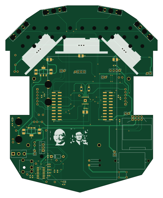
About the McDapBots KiCad TIMSPM0 PCB
McDapBots KiCad TIMSPM0 is an open source PCB design by DavidMe03, published on GitHub. It is a 2-layer board measuring 128.3 × 158.1 mm, with 79 components from 61 distinct parts.
Other key parts include the DRV8847PWPR, LM2937IMP-3.3/NOPB, SSD1306 and MAX712CSE. By type, the board carries 21 connectors, 19 test points, 14 capacitors, 14 resistors, 5 ICs and 1 transistor.
It belongs with the robotics & motion, displays & leds and sensors designs in this gallery.
From the project
McDap Capstone - KiCad project repository for TI MSPM0
This project was created as a capstone project for the University of Virginia Department of Electrical and Computer Engineering. Our goal was to create a small robot which could be programmed by students, for use as a teaching aide in an embedded systems course. This repository contains the hardware files specific to the robot's main board.
Authors - Colby Wise - Pratik Pandit - Austen Yun - David Merino - Marc Rosenthal
Main components on the McDapBots KiCad TIMSPM0
McDapBots KiCad TIMSPM0 bill of materials (BOM)
79 components, 61 distinct parts — part numbers from the project's BOM.
| Qty | Part | Footprint | Refs |
|---|---|---|---|
| 1 | DRV8847PWPR | SOP65P640X120-17N | U1 |
| 1 | LM2937IMP-3.3/NOPB LM2937IMP-5.0_NOPB | SOT230P700X180-4N | U2 |
| 1 | LM2937IMP-3.3/NOPB LM2937IMP-3.3_NOPB | SOT230P700X180-4N | U3 |
| 1 | SSD1306 https://www.amazon.com/s?k=SSD1306 | SSD1306 | U4 |
| 1 | MAX712CSE | SOIC-16_3.9x9.9mm_P1.27mm | U7 |
| 1 | TIP42A | TO-220-3_Vertical | Q1 |
| 1 | Bump0 | D2F-01L30-D3_5pin | J1 |
| 1 | Bump1 | D2F-01L30-D3_5pin | J2 |
| 2 | M20-8761042P LaunchPad | LaunchPad | J2_J4, J3_J1 |
| 1 | Bump2 | D2F-01L30-D3_5pin | J3 |
| 1 | Bump3 | D2F-01L30-D3_5pin | J4 |
| 1 | RSLK2 | RSLK_Chassis | J5 |
| 1 | 500SSP1S2M2QEA | 500SSP1S2M2QEA | J6 |
| 1 | XDS_VCC TP10 | PinHeader_1x02_P2.54mm_Vertical | J7 |
| 1 | LP3.3 | PinHeader_1x02_P2.54mm_Vertical | J8 |
| 1 | 54-00127 | TENSILITY_54-00127 | J9 |
| 1 | Reflector Support | PinHeader_1x04_P2.54mm_Vertical | J10 |
| 3 | M22-7130342 GP2Y0A41SK0F | SHDR3W50P0X200_1X3_650X240X440P | J11, J12, J13 |
| 1 | 7.2 | PinHeader_1x02_P2.54mm_Vertical | J15 |
| 1 | LP5.0 | PinHeader_1x02_P2.54mm_Vertical | J16 |
Show 41 more
| Qty | Part | Footprint | Refs |
|---|---|---|---|
| 1 | ELA | PinHeader_1x02_P2.54mm_Vertical | J17 |
| 1 | ERA | PinHeader_1x02_P2.54mm_Vertical | J18 |
| 1 | Voltage Display Port | SolderWire-0.15sqmm_1x02_P4mm_D0.5mm_OD1.5mm_Relief | J19 |
| 1 | Reflector I2C | PinHeader_1x04_P2.54mm_Vertical | J21 |
| 1 | ~ | PRT-14313 | DS1 |
| 1 | 590m | R_0603_1608Metric | R_Sense1 |
| 1 | TS02-66-50-BK-160-LCR-D | SW_TS02-66-50-BK-160-LCR-D | S1 |
| 1 | +5V | Testpoint_1x02_P2.54mm | TP1 |
| 1 | +7.2V | Testpoint_1x02_P2.54mm | TP2 |
| 1 | GND | Testpoint_1x02_P2.54mm | TP3 |
| 1 | +3.3V | Testpoint_1x02_P2.54mm | TP4 |
| 1 | BAT7.2V | Testpoint_1x1 | TP5 |
| 1 | BAT4.8V | Testpoint_1x1 | TP6 |
| 1 | MR+ | Testpoint_1x1 | TP7 |
| 1 | MR- | Testpoint_1x1 | TP8 |
| 1 | ML- | Testpoint_1x1 | TP9 |
| 1 | ML+ | Testpoint_1x1 | TP10 |
| 1 | NFault | Testpoint_1x1 | TP11 |
| 1 | +5V | Testpoint_1x1 | TP12 |
| 1 | GND | Testpoint_1x1 | TP13 |
| 1 | +3.3V | Testpoint_1x1 | TP16 |
| 1 | THI | Testpoint_1x1 | TP17 |
| 1 | TEMP | Testpoint_1x1 | TP18 |
| 1 | JACK+ | Testpoint_1x1 | TP19 |
| 1 | VREF | Testpoint_1x1 | TP20 |
| 1 | JACK- | Testpoint_1x1 | TP21 |
| 1 | APTD1608LSECK/J3-PF 3.3V | APT1608CGCK | LED1 |
| 1 | 1N4001 | D_DO-41_SOD81_P10.16mm_Horizontal | D1 |
| 8 | TAJB106K020RNJ 10uF | CAPPM3528X210N | C1, C2, C3, C4, C5, C6, C7, C8 |
| 1 | 0.1uF | C_0603_1608Metric | C9 |
| 2 | 10uF | C_0603_1608Metric | C11, C15 |
| 1 | 1uF | C_0603_1608Metric | C12 |
| 2 | 0.01uF | C_0603_1608Metric | C13, C14 |
| 5 | 4.7k | R_0603_1608Metric | R1, R2, R4, R13, R14 |
| 2 | 1.5k | R_0603_1608Metric | R3, R12 |
| 2 | 0.1 | R_1206_3216Metric | R5, R6 |
| 1 | 750 | R_0603_1608Metric | R7 |
| 1 | 1.4k | R_0603_1608Metric | R8 |
| 1 | 68K | R_0603_1608Metric | R9 |
| 1 | 22K | R_0603_1608Metric | R10 |
| 1 | 150 | R_0603_1608Metric | R11 |
McDapBots KiCad TIMSPM0 design files
The KiCad project lives in the DavidMe03/McDapBots_KiCad_TIMSPM0 repository on GitHub; these links point at the commit this page was built from.
McDapBots KiCad TIMSPM0: common questions
How big is the McDapBots KiCad TIMSPM0 PCB?
The McDapBots KiCad TIMSPM0 measures 128.3 × 158.1 mm, has 2 copper layers and is 1.6 mm thick.
How many components are on the McDapBots KiCad TIMSPM0?
79 components, from 61 distinct parts, with part numbers taken from the project's own BOM. The full bill of materials is listed on this page.
Where can I download the McDapBots KiCad TIMSPM0 design files?
From the DavidMe03/McDapBots_KiCad_TIMSPM0 repository on GitHub, which has the KiCad layout, the schematic and the BOM; the links under Design files point to each one.
Can I use the McDapBots KiCad TIMSPM0 design in my own project?
The repository has no license, so all rights stay with DavidMe03. Use it as a reference, and ask the author before reusing the design.
 atopile


 StuckAtPrototype
 AxxAxx
 Mentra-Community