
SMRRC SwitchAndSignal

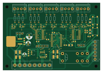
About the SMRRC SwitchAndSignal PCB
SMRRC SwitchAndSignal is an open source PIC PCB design by DavidMFlynn, published on GitHub under the MIT license. It is a 2-layer board measuring 98 × 68 mm, with 66 components from 25 distinct parts.
Its main chip is the PIC16F15345-I/SO, from the PIC family. Other key parts include the L78L05_SOT89, L7806, THVD1500, SN74HC259DR and SSM6N7002CFU. By type, the board carries 21 resistors, 14 ICs, 11 capacitors, 10 connectors, 7 diodes and 2 switches.
It belongs with the robotics & motion designs in this gallery.
From the project
Serial Model Railroad Control
This is a set of PCBs and software to control a model railroad with RS485 data buss.
Anamation Controller, 8 servos Block Detector, detects voltage across diode/resistor Optical Detector, broken beam or reflected beam
When a command packet is received from RX1 (RS485): Source=any, Destination=Me: Parse and Process the command. Send any requested data back to the sender on TX1 (RS485). Source=any, Destination=Master: Retransmit on TX2 (USB) Source=any, Destination= other than Master or Me do nothing.
Main components on the SMRRC SwitchAndSignal
SMRRC SwitchAndSignal bill of materials (BOM)
66 components, 25 distinct parts.
| Qty | Part | Footprint | Refs |
|---|---|---|---|
| 1 | L78L05_SOT89 | SOT-89-3 | U1 |
| 1 | L7806 | TO-263-2 | U2 |
| 1 | PIC16F15345-I/SO | SOIC-20W_7.5x12.8mm_P1.27mm | U3 |
| 1 | THVD1500 | SOIC-8_3.9x4.9mm_P1.27mm | U4 |
| 2 | SN74HC259DR | SOIC-16W_5.3x10.2mm_P1.27mm | U5, U6 |
| 8 | SSM6N7002CFU | SOT-363_SC-70-6_Handsoldering | U7, U8, U9, U10, U11, U12, U13, U14 |
| 1 | Conn_01x05 | PinHeader_1x05_P2.54mm_Vertical | J1 |
| 1 | Conn_01x03 | PinSocket_1x03_P2.54mm_Vertical | J2 |
| 1 | Conn_01x03 | PinHeader_1x03_P2.54mm_Vertical | J3 |
| 1 | Conn_01x08_Socket | TerminalBlock_MaiXu_MX126-5.0-08P_1x08_P5.00mm | J4 |
| 1 | Conn_01x06 | TerminalBlock_MetzConnect_Type059_RT06306HBWC_1x06_P3.50mm_Horizontal | J5 |
| 5 | Conn_01x04 | TerminalBlock_Phoenix_PT-1,5-4-3.5-H_1x04_P3.50mm_Horizontal | J6, J7, J8, J9, J10 |
| 1 | J114AF | Relay_DPDT_Finder_40.52 | K1 |
| 2 | SW_Push | SW_SPST_PTS645 | SW1, SW2 |
| 4 | SMA | D_SMA_Handsoldering | D1, D2, D6, D7 |
| 3 | LED_Filled | D_1206_3216Metric_Pad1.42x1.75mm_HandSolder | D3, D4, D5 |
| 1 | 10uf | CP_Radial_D4.0mm_P2.00mm | C1 |
| 1 | 33uF | CP_Radial_D5.0mm_P2.00mm | C2 |
| 6 | 0.1uf | C_0805_2012Metric_Pad1.18x1.45mm_HandSolder | C3, C5, C7, C8, C10, C11 |
| 2 | .1uF | C_0805_2012Metric_Pad1.18x1.45mm_HandSolder | C4, C6 |
Show 5 more
| Qty | Part | Footprint | Refs |
|---|---|---|---|
| 1 | 220uF | CP_Radial_D6.3mm_P2.50mm | C9 |
| 3 | 1K0 | R_0805_2012Metric_Pad1.20x1.40mm_HandSolder | R1, R3, R5 |
| 2 | 47K | R_0805_2012Metric_Pad1.20x1.40mm_HandSolder | R2, R4 |
| 1 | 220 | R_0805_2012Metric_Pad1.20x1.40mm_HandSolder | R6 |
| 15 | 1K0 | R_Axial_DIN0204_L3.6mm_D1.6mm_P7.62mm_Horizontal | R7, R8, R9, R10, R11, R12, R13, R14 +7 |
SMRRC SwitchAndSignal design files
The KiCad project lives in the DavidMFlynn/SerialMRRC repository on GitHub; these links point at the commit this page was built from.
SMRRC SwitchAndSignal: common questions
What microcontroller does the SMRRC SwitchAndSignal use?
The SMRRC SwitchAndSignal is built around the PIC16F15345-I/SO, from the PIC family.
How big is the SMRRC SwitchAndSignal PCB?
The SMRRC SwitchAndSignal measures 98 × 68 mm, has 2 copper layers and is 1.6 mm thick.
How many components are on the SMRRC SwitchAndSignal?
66 components, from 25 distinct parts. The full bill of materials is listed on this page.
Where can I download the SMRRC SwitchAndSignal design files?
From the DavidMFlynn/SerialMRRC repository on GitHub, which has the KiCad layout and the schematic; the links under Design files point to each one.
Can I use the SMRRC SwitchAndSignal design in my own project?
Yes, under the terms of its MIT license, which DavidMFlynn chose for the repository.
Can I test firmware for the SMRRC SwitchAndSignal without the hardware?
Yes. HardLabs builds a simulation of the board from its netlist and BOM, so you can run and debug PIC firmware against it before you order a PCB.
More boards in SerialMRRC
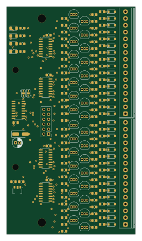
Input32DC
66 × 117 mm218 parts2LMIT1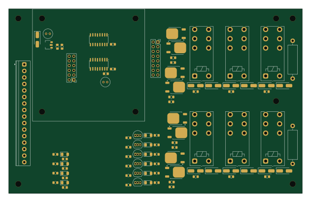
Block Relay Daughter
157.5 × 99.1 mm92 parts2LMIT1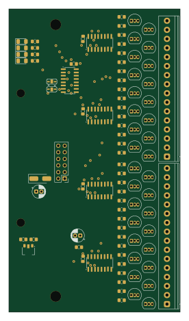
Output32DC
66 × 117 mm92 parts2LMIT1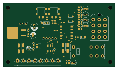 PIC
PICSMRRC Switch
95.4 × 54.4 mm53 parts2LMIT1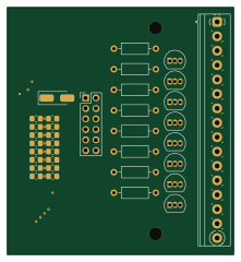
Lights
55 × 60 mm35 parts2LMIT1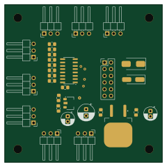
Seial Model Railroad Control
60 × 60 mm30 parts2LMIT1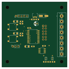 PIC
PICSMRRC
60 × 60 mm28 parts2LMIT1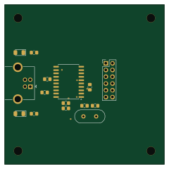
SMRRC USB
60 × 60 mm15 parts2LMIT1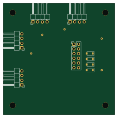
SMRRC PacketSerial
60 × 60 mm9 parts2LMIT1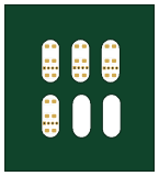
Signal Head 3
36 × 40 mm4 parts2LMIT1
Similar boards
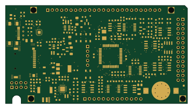 PIC
PICPslab hardware
fossasia
99 × 53.3 mm187 parts4LApache-2.01.7k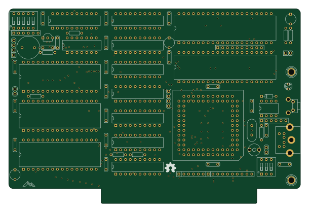 PIC
PICMicro 8088
skiselev
152.4 × 101.6 mm71 partsGPL-3.0414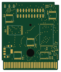 PIC
PICGB-MBCTEST
Gekkio
51.4 × 61 mm32 parts2LCC-BY-4.0376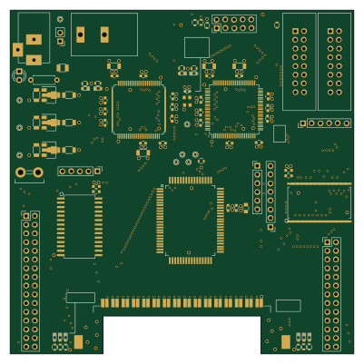 PIC
PICGB-BENCH-G1
100 × 100 mm98 parts4LCC-BY-4.0376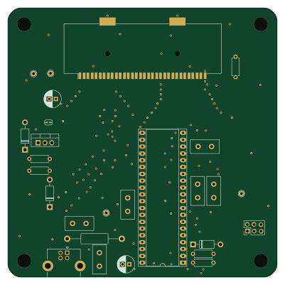 PIC
PICGB-CARTPP-DIY
100 × 100 mm22 parts2LCC-BY-4.0376 PIC
PICGB-LIVE32
51.4 × 61 mm46 parts4LCC-BY-4.0376