
Rtl8367-switch

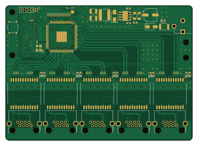
About the Rtl8367-switch PCB
Rtl8367-switch is an open source PCB design by Deco025, published on GitHub under the CERN-OHL-S-2.0 license. It is a 4-layer board measuring 100 × 72 mm, with 219 components from 52 distinct parts.
Other key parts include the TPS54331DDAR, TPS62130ARGTR, TPS3808G30DBVR, RTL8367RB-VB-CG and AT24C256C-SSHL-T. By type, the board carries 93 resistors, 77 capacitors, 15 ICs, 14 diodes, 7 connectors and 5 transformers.
From the project
Five-port gigabit unmanaged Ethernet switch based on the Realtek RTL8367RB - 4-layer KiCad 10 design with fabrication outputs
- 主要指标 - 系统结构 - 仓库结构 - 打开工程 - 打样与装配 - 设计要点 - 设计检查与装配注意事项 - 许可证 - 致谢
- 5 个网口都用芯片内置的 PHY,MDI 从芯片直连变压器,中间没有其他器件。 - 变压器芯片侧的中心抽头各接 0.1 µF 到地,另外预留一个 0 Ω 到 +3V3A 的位置(默认不贴)。 - 线缆侧中心抽头各经 75 Ω 汇到一点,再经 1 nF / 2 kV 接屏蔽地 CHASSIS(Bob Smith 终端)。CHASSIS 与 GND 之间有一颗 1 nF 电容。 - 每对差分线旁预留了 ESD 保护(TPD4E02B04,默认不贴)。
1. 安装 KiCad 10.0 或更新版本。 2. 打开 rtl8367-switch.kicadpro。RTL8367RB、H5007NL 和 RJ45 的符号与封装在 lib/ 里,工程的库表已经指向它们;其余来自 KiCad 官方库。 3. 3D 模型(可选):有 6 种器件的 3D 模型不在 KiCad 官方库里,版权也不允许随仓库再分发。按 3dmodels/README.md 下载到 3dmodels/,3D 查看器(Alt+3`)里就能看到完整外观。不下载也不影响原理图、PCB 和生产文件。
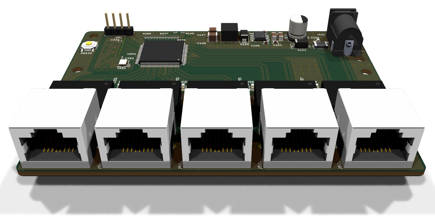
Main components on the Rtl8367-switch
Rtl8367-switch bill of materials (BOM)
219 components, 52 distinct parts — part numbers from the project's BOM.
| Qty | Part | Footprint | Refs |
|---|---|---|---|
| 1 | TPS54331DDAR TPS54331DDA | Texas_HSOP-8-1EP_3.9x4.9mm_P1.27mm_ThermalVias | U101 |
| 1 | TPS62130ARGTR TPS62130A | VQFN-16-1EP_3x3mm_P0.5mm_EP1.68x1.68mm_ThermalVias | U102 |
| 1 | TPS3808G30DBVR | SOT-23-6 | U103 |
| 1 | RTL8367RB-VB-CG | LQFP-128-1EP_14x14mm_P0.4mm_EP5.5x5.5mm_ThermalVias | U201 |
| 1 | AT24C256C-SSHL-T AT24C256C | SOIC-8_3.9x4.9mm_P1.27mm | U251 |
| 10 | TPD4E02B04DQAR TPD4E02B04DQA | USON-10_2.5x1.0mm_P0.5mm | U301, U302, U401, U402, U501, U502, U601, U602 +2 |
| 1 | X322525MOB4SI 25MHz | Crystal_SMD_3225-4Pin_3.2x2.5mm | Y251 |
| 1 | PJ-102AH | BarrelJack_CUI_PJ-102AH_Horizontal | J101 |
| 1 | J_DBG | PinHeader_1x04_P2.54mm_Vertical | J251 |
| 5 | R-RJ45R08P-B000 | RJ45_Ckmtw_R-RJ45R08P-B000_Horizontal | J301, J401, J501, J601, J701 |
| 1 | 1812L075/33DR | Fuse_1812_4532Metric | F101 |
| 1 | TS-1187A-B-A-B RESET | SW_Push_1P1T_XKB_TS-1187A | SW101 |
| 5 | H5007NL | Pulse_H5007NL | T301, T401, T501, T601, T701 |
| 2 | SS34 | D_SMA | D101, D103 |
| 1 | SMBJ15A | D_SMB | D102 |
| 6 | LTST-C193TGKT-5A Green | LED_0603_1608Metric | D104, D251, D253, D255, D257, D259 |
| 5 | KT-0603Y Yellow | LED_0603_1608Metric | D252, D254, D256, D258, D260 |
| 3 | 0R | R_0603_1608Metric | FB201, FB202, FB203 |
| 1 | SWPA6045S6R8MT 6.8uH | L_Sunlord_SWPA6045S | L101 |
| 1 | SWPA4030S2R2MT 2.2uH | L_Sunlord_SWPA4030S | L102 |
Show 32 more
| Qty | Part | Footprint | Refs |
|---|---|---|---|
| 1 | 47uF | CP_Elec_6.3x7.7 | C101 |
| 2 | 4.7uF | C_1206_3216Metric | C102, C103 |
| 1 | 10nF | C_0603_1608Metric | C104 |
| 2 | 22nF | C_0603_1608Metric | C105, C113 |
| 1 | 100nF | C_0603_1608Metric | C106 |
| 2 | 47uF | C_1210_3225Metric | C107, C108 |
| 1 | 1nF | C_0603_1608Metric | C109 |
| 1 | 47pF | C_0603_1608Metric | C110 |
| 5 | 10uF | C_0805_2012Metric | C111, C207, C218, C222, C230 |
| 50 | 100nF | C_0402_1005Metric | C112, C116, C201, C202, C203, C204, C205, C206 +42 |
| 2 | 22uF | C_0805_2012Metric | C114, C115 |
| 6 | 1nF | C_1206_3216Metric | C117, C305, C405, C505, C605, C705 |
| 1 | 1uF | C_0603_1608Metric | C232 |
| 2 | 18pF | C_0402_1005Metric | C251, C252 |
| 1 | 332k | R_0603_1608Metric | R101 |
| 1 | 68.1k | R_0603_1608Metric | R102 |
| 1 | 0R | R_0603_1608Metric | R103 |
| 1 | 10.2k | R_0603_1608Metric | R104 |
| 1 | 3.24k | R_0603_1608Metric | R105 |
| 1 | 29.4k | R_0603_1608Metric | R106 |
| 1 | 30.1k | R_0402_1005Metric | R107 |
| 1 | 80.6k | R_0402_1005Metric | R108 |
| 2 | 10k | R_0402_1005Metric | R109, R111 |
| 1 | 100k | R_0402_1005Metric | R110 |
| 1 | 1.5k | R_0402_1005Metric | R112 |
| 1 | 1M | R_0603_1608Metric | R113 |
| 1 | 2.49k | R_0402_1005Metric | R201 |
| 13 | 4.7k | R_0402_1005Metric | R251, R252, R253, R254, R257, R258, R261, R262 +5 |
| 10 | 470R | R_0402_1005Metric | R255, R256, R259, R260, R263, R264, R267, R268 +2 |
| 16 | 1k | R_0402_1005Metric | R274, R275, R276, R277, R278, R279, R280, R281 +8 |
| 20 | 0R | R_0402_1005Metric | R301, R302, R303, R304, R401, R402, R403, R404 +12 |
| 20 | 75R | R_0603_1608Metric | R305, R306, R307, R308, R405, R406, R407, R408 +12 |
Rtl8367-switch design files
The KiCad project lives in the Deco025/rtl8367-switch repository on GitHub; these links point at the commit this page was built from.
Rtl8367-switch: common questions
How big is the Rtl8367-switch PCB?
The Rtl8367-switch measures 100 × 72 mm, has 4 copper layers and is 1.58 mm thick.
How many components are on the Rtl8367-switch?
219 components, from 52 distinct parts, with part numbers taken from the project's own BOM. The full bill of materials is listed on this page.
Where can I download the Rtl8367-switch design files?
From the Deco025/rtl8367-switch repository on GitHub, which has the KiCad layout, the schematic and the BOM; the links under Design files point to each one.
Can I use the Rtl8367-switch design in my own project?
Yes, under the terms of its CERN-OHL-S-2.0 license, which Deco025 chose for the repository.