
Octobot

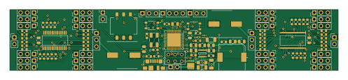
About the Octobot PCB
Octobot is an open source AVR/Arduino PCB design by Deivid-Negoita, published on GitHub under the MIT license. It is a 4-layer board measuring 124 × 23 mm, with 120 components from 33 distinct parts.
Its main chip is the ATMEGA32U4-M, from the AVR/Arduino family. Other key parts include the SY8303AIC, PCA9685PW/Q900_118 and AVR-ISP. By type, the board carries 54 resistors, 34 connectors, 17 capacitors, 5 ICs, 4 diodes and 3 switches.
It belongs with the robotics & motion, rf & radio and power & battery designs in this gallery.
From the project
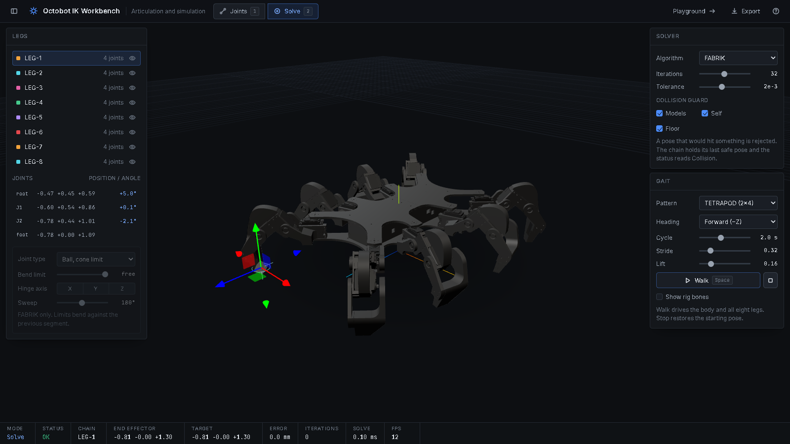
An eight-legged walking robot I built end to end: chassis CAD, a 24-servo ATmega32U4 controller board, the firmware, and a browser IK workbench you can drive it from.
An eight-legged walking robot with 24 servos, built end to end. The chassis and legs are CAD. A custom ATmega32U4 board drives every servo. A browser workbench rigs the CAD model and solves its inverse kinematics.
The workbench runs live in the browser: . It needs no install and no build step.
The robot carries environmental-monitoring, 3D-scanning and speleological payloads. Those payloads need the legs to place feet accurately on uneven ground, which a fixed gait cannot do. The kinematics workbench in this repository exists to solve that.
Main components on the Octobot
Octobot bill of materials (BOM)
120 components, 33 distinct parts — part numbers from the project's BOM.
| Qty | Part | Footprint | Refs |
|---|---|---|---|
| 1 | SY8303AIC | SOT65P280X110-8N | IC1 |
| 2 | PCA9685PW/Q900_118 | SOP65P640X110-28N | U1, U2 |
| 1 | ATMEGA32U4-M ATmega32U4-M | QFN-44-1EP_7x7mm_P0.5mm_EP5.2x5.2mm | U3 |
| 1 | AVR-ISP | AVR-ISP | U4 |
| 1 | RQ3E075ATTB | RQ3E075ATTB | Q1 |
| 1 | CRYSTAL_GND24 Crystal_GND24 | CRYSTAL-SMD-5X3.2-4PAD | Y1 |
| 1 | 47346-0001 | MOLEX_47346-0001 | J1 |
| 28 | CONN_01X03_PIN Conn_01x03_Pin | PinHeader_1x03_P2.54mm_Vertical | J2, J3, J4, J5, J6, J7, J8, J10 +20 |
| 4 | 1X2 1x2 | PinHeader_1x02_P2.54mm_Vertical | J9, J16, J31, J34 |
| 1 | CONN_01X04_PIN Conn_01x04_Pin | PinHeader_1x04_P2.54mm_Vertical | J15 |
| 2 | TL3365AF180QG | SW_TL3365AF180QG | S1, S2 |
| 1 | DS04-254-2-03BK-SMT | DS04254203BKSMT | S3 |
| 3 | LED | LED_0201_0603Metric | D1, D3, D4 |
| 1 | HPZR-C10X | HPZRC10X | D5 |
| 1 | 7447713047 4,7 uH | 7447714220 | L1 |
| 2 | 18PF 18pF | C_0603_1608Metric | C1, C3 |
| 2 | 1UF 1uF | C_0805_2012Metric | C2, C8 |
| 6 | 10UF 10uF | C_0805_2012Metric | C4, C5, C18, C19, C22, C23 |
| 2 | 875075161013 | CAPAE1030X1240N | C6, C9 |
| 1 | 0.1UF 0.1uF | C_0805_2012Metric | C7 |
Show 13 more
| Qty | Part | Footprint | Refs |
|---|---|---|---|
| 1 | 12 pF | C_1206_3216Metric | C16 |
| 2 | 0,1uF | C_0603_1608Metric | C17, C21 |
| 1 | 10NF 10nF | C_1206_3216Metric | C20 |
| 20 | 10K | R_0603_1608Metric | R1, R5, R8, R10, R14, R16, R17, R18 +12 |
| 2 | 22 Ohm | R_0603_1608Metric | R2, R3 |
| 1 | 10KOHM 10KOhm | R_0603_1608Metric | R4 |
| 1 | 1KOHM 1KOhm | R_0603_1608Metric | R6 |
| 2 | 1K | R_0402_1005Metric | R7, R9 |
| 1 | 110K Ohm | R_0805_2012Metric | R11 |
| 1 | 15K Ohm | R_0805_2012Metric | R12 |
| 1 | 100K Ohm | R_0805_2012Metric | R13 |
| 1 | 100K | R_1206_3216Metric | R15 |
| 24 | 220 Ohm | R_0603_1608Metric | R31, R32, R33, R34, R35, R36, R37, R38 +16 |
Octobot design files
The KiCad project lives in the Deivid-Negoita/octobot repository on GitHub; these links point at the commit this page was built from.
Octobot: common questions
What microcontroller does the Octobot use?
The Octobot is built around the ATMEGA32U4-M, from the AVR/Arduino family.
How big is the Octobot PCB?
The Octobot measures 124 × 23 mm, has 4 copper layers and is 1.6 mm thick.
How many components are on the Octobot?
120 components, from 33 distinct parts, with part numbers taken from the project's own BOM. The full bill of materials is listed on this page.
Where can I download the Octobot design files?
From the Deivid-Negoita/octobot repository on GitHub, which has the KiCad layout, the schematic and the BOM; the links under Design files point to each one.
Can I use the Octobot design in my own project?
Yes, under the terms of its MIT license, which Deivid-Negoita chose for the repository.
Can I test firmware for the Octobot without the hardware?
Yes. HardLabs builds a simulation of the board from its netlist and BOM, so you can run and debug AVR/Arduino firmware against it before you order a PCB.
Similar boards
 AVR/Arduino
V4
stuartpittaway
30 × 50 mm38 parts2LCC-BY-NC-4.01.1k AVR/Arduino
ModuleV450
30 × 61.4 mm39 parts2LCC-BY-NC-4.01.1k AVR/Arduino
Easyduino Atmega Nano
Hanqaqa
43.4 × 18 mm30 parts4LCERN-OHL-P-2.0746 AVR/Arduino
Easyduino Atmega
68.8 × 53.6 mm35 parts4LCERN-OHL-P-2.0746 AVR/Arduino
UsbGpib
xyphro
54 × 15 mm21 parts2LMIT683 AVR/Arduino
Lumberjack
peej
284.7 × 94.2 mm149 parts2LMIT402