
Transmitter Schematics

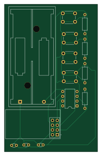
About the Transmitter Schematics PCB
Transmitter Schematics is an open source AVR/Arduino PCB design by devansh2004sharma-tech, published on GitHub. It is a 2-layer board measuring 49.5 × 78 mm, with 14 components from 7 distinct parts.
Its main chip is the ATtiny85-20P, from the AVR/Arduino family. Other key parts include the NRF24L01_Breakout. By type, the board carries 4 switches, 4 resistors, 3 capacitors, 2 ICs and 1 battery holder.
It belongs with the iot & wireless and robotics & motion designs in this gallery.
From the project
KiCad schematics and PCB layouts for a wireless RC car — ATtiny85 remote (TX) and ATmega328P motor-control receiver (RX), linked over NRF24L01+.
A two-board wireless RC car electronics design, built as a solo project: a compact ATtiny85-based handheld remote transmitting over an NRF24L01+ 2.4GHz radio link, and an ATmega328P-based receiver board that decodes commands and drives two DC motors through a DRV8833 dual H-bridge. Designed end-to-end in KiCad — schematics, PCB layout, and manufacturing (gerber) files for both boards.
Main components on the Transmitter Schematics
Transmitter Schematics bill of materials (BOM)
14 components, 7 distinct parts.
| Qty | Part | Footprint | Refs |
|---|---|---|---|
| 1 | ATtiny85-20P | DIP-8_W7.62mm | U1 |
| 1 | NRF24L01_Breakout | nRF24L01_Breakout | U2 |
| 1 | Battery | BatteryHolder_Keystone_2468_2xAAA | BT1 |
| 4 | SW_Push | SW_PUSH_6mm | SW1, SW2, SW3, SW4 |
| 2 | C | C_Disc_D3.0mm_W1.6mm_P2.50mm | C1, C3 |
| 1 | C_Polarized | C_Disc_D3.0mm_W1.6mm_P2.50mm | C2 |
| 4 | R | R_Axial_DIN0207_L6.3mm_D2.5mm_P10.16mm_Horizontal | R1, R2, R3, R4 |
Transmitter Schematics design files
The KiCad project lives in the devansh2004sharma-tech/nrf24-rc-car-controller repository on GitHub; these links point at the commit this page was built from.
Transmitter Schematics: common questions
What microcontroller does the Transmitter Schematics use?
The Transmitter Schematics is built around the ATtiny85-20P, from the AVR/Arduino family.
How big is the Transmitter Schematics PCB?
The Transmitter Schematics measures 49.5 × 78 mm, has 2 copper layers and is 1.6 mm thick.
How many components are on the Transmitter Schematics?
14 components, from 7 distinct parts. The full bill of materials is listed on this page.
Where can I download the Transmitter Schematics design files?
From the devansh2004sharma-tech/nrf24-rc-car-controller repository on GitHub, which has the KiCad layout; the links under Design files point to each one.
Can I use the Transmitter Schematics design in my own project?
The repository has no license, so all rights stay with devansh2004sharma-tech. Use it as a reference, and ask the author before reusing the design.
Can I test firmware for the Transmitter Schematics without the hardware?
Yes. HardLabs builds a simulation of the board from its netlist and BOM, so you can run and debug AVR/Arduino firmware against it before you order a PCB.
More boards in nrf24-rc-car-controller
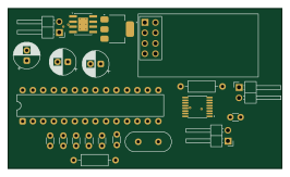
Similar boards
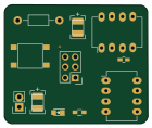 AVR/Arduino
Magspoof
samyk
35 × 29 mm11 parts2LNo license4.2k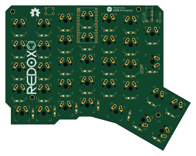 AVR/Arduino
Redox keyboard
mattdibi
162.2 × 126.5 mm77 parts2LMIT2.0k AVR/Arduino
Labrador
espotek-org
36.8 × 34.7 mm75 parts2LNo license1.2k AVR/Arduino
V4
stuartpittaway
30 × 50 mm38 parts2LCC-BY-NC-4.01.1k AVR/Arduino
ModuleV450
30 × 61.4 mm39 parts2LCC-BY-NC-4.01.1k AVR/Arduino
Discipline
coseyfannitutti
304.9 × 122.8 mm170 parts2LCC-BY-NC-4.01.0k