
Solderbit segment

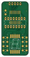
About the Solderbit segment PCB
Solderbit segment is an open source PCB design by devices-lab, published on GitHub under the GPL-3.0 license. It is a 2-layer board measuring 25 × 50 mm, with 13 components from 6 distinct parts.
Other key parts include the PCF8574AT and PCF8574N. By type, the board carries 8 resistors, 2 ICs, 1 connector and 1 capacitor.
It belongs with the displays & leds and dev boards & breakouts designs in this gallery, and the repository also holds 1 earlier revision of it.
From the project
Learn-to-solder kit using a 7-segment display
The solder:bit Segment is a kit for learning to solder with surface-mount (SMT) components. When assembled, the device can display a single digit on a 7-segment display. It works with any microcontroller that communicates over the I²C protocol.
This soldering kit is designed to accommodate a wide range of soldering abilities. The I/O expander is available in two different packages. The PCF8574AT in the SO-16 package is smaller and more challenging to solder, while the PCF8574N in the DIP-16 package is larger and through-hole (THT), making it more accessible for novices. The same printed…
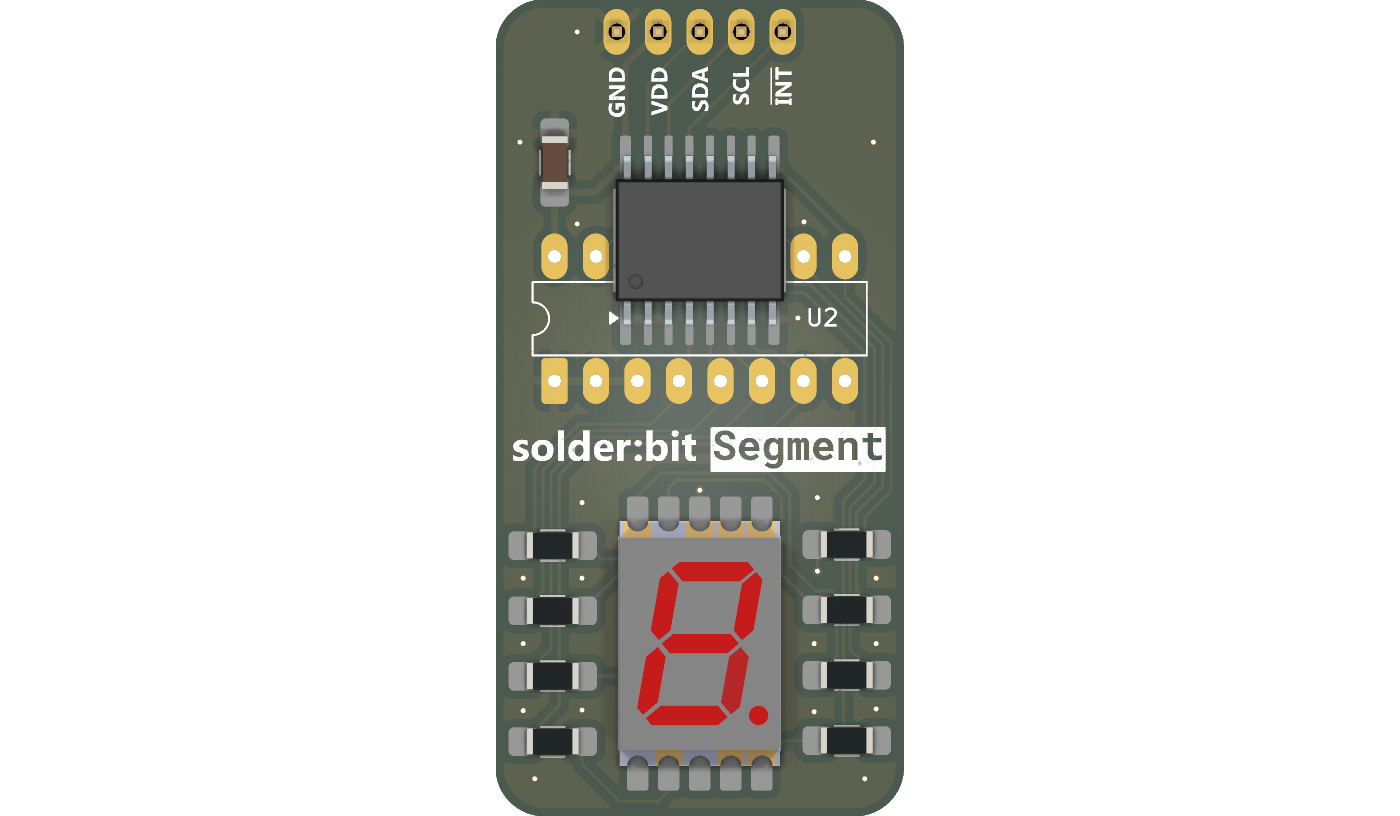
Main components on the Solderbit segment
Solderbit segment bill of materials (BOM)
13 components, 6 distinct parts.
| Qty | Part | Footprint | Refs |
|---|---|---|---|
| 1 | PCF8574AT | SO-16 | U1 |
| 1 | PCF8574N | DIP-16 | U2 |
| 1 | Conn_01x05_Pin | PinHeader_1x05_P2.54mm_Vertical | J1 |
| 1 | VDMO10A0 | VDMR10 | DS1 |
| 1 | 1uF | C_1206 | C1 |
| 8 | 150R | R_1206 | R1, R2, R3, R4, R5, R6, R7, R8 |
Solderbit segment design files
The KiCad project lives in the devices-lab/solderbit-segment repository on GitHub; these links point at the commit this page was built from.
Solderbit segment: common questions
How big is the Solderbit segment PCB?
The Solderbit segment measures 25 × 50 mm, has 2 copper layers and is 1.6 mm thick.
How many components are on the Solderbit segment?
13 components, from 6 distinct parts. The full bill of materials is listed on this page.
Where can I download the Solderbit segment design files?
From the devices-lab/solderbit-segment repository on GitHub, which has the KiCad layout and the schematic; the links under Design files point to each one.
Can I use the Solderbit segment design in my own project?
Yes, under the terms of its GPL-3.0 license, which devices-lab chose for the repository.
Earlier revisions in the repo: solderbit-segment
Similar boards
BM28B0.6-24DSBreakout
scottbez1
15.2 × 35.6 mm3 parts2LApache-2.022.2k
View screen
35 × 35 mm12 parts2LApache-2.022.2k
LevelShifterBreakout
15.2 × 20.3 mm5 parts2LApache-2.022.2k
View base
81.2 × 81.2 mm81 parts2LApache-2.022.2k
Display eval
byrantech
52.1 × 22.6 mm12 parts4LMIT4.3k
ChainlinkBase
98.4 × 190.5 mm119 parts2LApache-2.04.2k