
Arm header pinout board

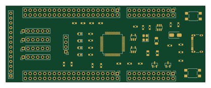
About the Arm header pinout board
Arm header pinout board is an open source NXP PCB design by devKOff, published on GitHub under the Custom license license. It is a 2-layer board measuring 104.4 × 40 mm, with 52 components from 28 distinct parts.
Its main chip is the LPC2148FBD64, from the NXP family. Other key parts include the USBLC6-2SC6 and AP2112K-3.3. By type, the board carries 14 resistors, 13 capacitors, 10 connectors, 5 diodes, 3 ICs and 2 transistors.
It belongs with the dev boards & breakouts and usb & debug tools designs in this gallery.
From the project
Custom LPC2148 ARM7 development board designed in KiCad with USB-C, 5V protection, 3.3V regulation, USB ESD protection, crystal oscillator, reset, ISP/UART programming, JTAG, GPIO, I2C, SPI, ADC, DAC, LEDs, test points, and expansion headers for embedded development.
A custom breakout and header pinout board designed for ARM microcontroller development, providing structured signal routing, power distribution, and debugging access points.
The ARM Header Pinout Board is engineered to simplify prototyping and peripheral interfacing for ARM-based microcontrollers. It breaks out all core GPIO, communication buses (SPI, I2C, UART), and power rails into clean, labeled standard pin headers, minimizing wiring clutter on the breadboard.
Main components on the Arm header pinout board
Arm header pinout board bill of materials (BOM)
52 components, 28 distinct parts — part numbers from the project's BOM.
| Qty | Part | Footprint | Refs |
|---|---|---|---|
| 1 | LPC2148FBD64 | LQFP-64_10x10mm_P0.5mm | U1 |
| 1 | USBLC6-2SC6 | SOT-23-6 | U2 |
| 1 | AP2112K-3.3 | SOT-23-5 | U3 |
| 1 | AO3401A | SOT-23-5 | Q1 |
| 1 | BC847 | SOT-23 | Q2 |
| 1 | 12MHz | Crystal_SMD_3225-4Pin_3.2x2.5mm | Y1 |
| 1 | USB_C_Receptacle_USB2.0_16P | USB_C_Receptacle_GCT_USB4105-xx-A_16P_TopMnt_Horizontal | J1 |
| 4 | Conn_01x06 | PinHeader_1x06_P2.54mm_Vertical | J2, J6, J7, J8 |
| 2 | Conn_02x10_Odd_Even | PinHeader_2x10_P2.54mm_Vertical | J3, J9 |
| 1 | Conn_02x20_Odd_Even | PinHeader_2x20_P2.54mm_Vertical | J4 |
| 1 | GPIO_PORT1 | PinHeader_2x20_P2.54mm_Vertical | J5 |
| 1 | Conn_01x04 | PinHeader_1x04_P2.54mm_Vertical | J10 |
| 1 | 500mA PTC | Fuse_1206_3216Metric | F1 |
| 2 | SW_Push | SW_SPST_TL3305A | SW1, SW2 |
| 1 | SMBJ5.0A | D_SMA | D1 |
| 4 | LED | LED_0603_1608Metric | D2, D3, D4, D5 |
| 1 | Ferrite bead | L_0603_1608Metric | FB1 |
| 2 | 18pF* | R_0603_1608Metric | C1, C2 |
| 2 | 10µF | C_0805_2012Metric | C3, C5 |
| 8 | 100nF | C_0603_1608Metric | C4, C6, C7, C8, C9, C10, C12, C16 |
Show 8 more
| Qty | Part | Footprint | Refs |
|---|---|---|---|
| 1 | 4.7µF | C_0603_1608Metric | C11 |
| 2 | 5.1kΩ | R_0603_1608Metric | R1, R2 |
| 2 | 33Ω | R_0603_1608Metric | R3, R4 |
| 1 | 100kΩ | R_0603_1608Metric | R5 |
| 3 | 10kΩ | R_0603_1608Metric | R6, R7, R17 |
| 4 | 1k | R_0603_1608Metric | R10, R11, R12, R13 |
| 1 | 1.5kΩ | SOT-23 | R16 |
| 1 | 47Ω | R_Array_SIP14 | RN1 |
Arm header pinout board design files
The KiCad project lives in the devKOff/arm-header-pinout-board repository on GitHub; these links point at the commit this page was built from.
- Layoutproject_3.kicad_pcb
- Schematicproject_3.kicad_sch
- BOMbom/bom.csv
Arm header pinout board: common questions
What microcontroller does the Arm header pinout board use?
The Arm header pinout board is built around the LPC2148FBD64, from the NXP family.
How big is the Arm header pinout board?
The Arm header pinout board measures 104.4 × 40 mm, has 2 copper layers and is 1.6 mm thick.
How many components are on the Arm header pinout board?
52 components, from 28 distinct parts, with part numbers taken from the project's own BOM. The full bill of materials is listed on this page.
Where can I download the Arm header pinout board design files?
From the devKOff/arm-header-pinout-board repository on GitHub, which has the KiCad layout, the schematic and the BOM; the links under Design files point to each one.
Can I use the Arm header pinout board design in my own project?
It is published under Custom license, which limits how it may be reused; read the license before building on it.
Can I test firmware for the Arm header pinout board without the hardware?
Yes. HardLabs builds a simulation of the board from its netlist and BOM, so you can run and debug NXP firmware against it before you order a PCB.
Similar boards
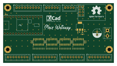 NXP
32Bit shift register
MaltWhiskey
100 × 54 mm56 parts4LNo license763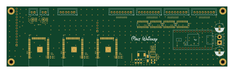 NXP
Mega-Cube-Board
200 × 54 mm100 parts4LNo license763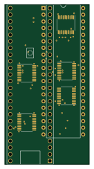 NXP
MCL6809
MicroCoreLabs
32.3 × 61 mm7 parts4LNo license532 NXP
MCL68
31.6 × 84.1 mm13 parts4LNo license532 NXP
MCL65+
72.6 × 64.1 mm6 parts2LNo license532 NXP
MCLZ8
37.1 × 61.5 mm6 parts4LNo license532