
Electric-Drive-Systems

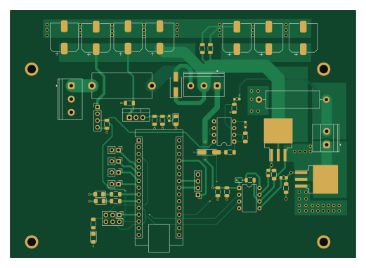
About the Electric-Drive-Systems PCB
Electric-Drive-Systems is an open source AVR/Arduino PCB design by DileepChilla, published on GitHub under the CC-BY-4.0 license. It is a 2-layer board measuring 130 × 93 mm, with 55 components from 33 distinct parts.
Its main chip is the Arduino_Nano_v3.x, from the AVR/Arduino family. Other key parts include the L7812CV, LM358 and IR2104. By type, the board carries 17 capacitors, 13 resistors, 10 connectors, 8 diodes, 3 ICs and 2 transistors.
It belongs with the robotics & motion designs in this gallery.
From the project
motor-control | power-electronics | kicad | atmega328p | ir2104 | irfz44n | pwm | embedded-systems | simulink | gate-driver
IR2104 half-bridge · 2× IRFZ44N · ATmega328P closed-loop control
Design, simulation, PCB layout, firmware and bench validation of a complete motor drive for a MY1016 24 V 250 W brushed DC motor. Built for ELT10140 Electric Drive Systems, Westsächsische Hochschule Zwickau, summer semester 2026.
A single-quadrant (unidirectional) drive with hardware and software overcurrent protection, soft-start, stall detection and a five-state supervisory state machine. The design was carried through the full V-cycle: analytical sizing → SPICE/VSM co-simulation → averaged-model verification in Simulink →…
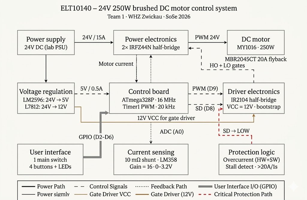
Main components on the Electric-Drive-Systems
Electric-Drive-Systems bill of materials (BOM)
55 components, 33 distinct parts — part numbers from the project's BOM.
| Qty | Part | Footprint | Refs |
|---|---|---|---|
| 1 | L7812CV | TO-220-3_Vertical | U1 |
| 1 | LM358 | DIP-8_W7.62mm | U2 |
| 1 | IR2104 | DIP-8_W7.62mm | U3 |
| 1 | Arduino_Nano_v3.x | Arduino_Nano | A1 |
| 2 | Q_NMOS_GDS | TO-263-3_TabPin2 | Q1, Q2 |
| 2 | Screw_Terminal_01x03 | TerminalBlock_Phoenix_PT-1,5-3-5.0-H_1x03_P5.00mm_Horizontal | J1, J2 |
| 1 | LM2596_MODULE | PinHeader_1x04_P2.54mm_Vertical | J3 |
| 1 | Motor | TerminalBlock_Phoenix_MKDS-1,5-2-5.08_1x02_P5.08mm_Horizontal | J4 |
| 3 | Conn_01x02_Pin | PinHeader_1x02_P2.54mm_Vertical | J5, J6, J7 |
| 1 | BTN_ON | PinHeader_1x02_P2.54mm_Vertical | J8 |
| 1 | Conn_02x03_Odd_Even | PinHeader_2x03_P2.54mm_Vertical | J9 |
| 1 | OLED Display 0.96" (SSD1306 | PinHeader_1x04_P2.54mm_Vertical | J10 |
| 1 | 15A T | Fuseholder_Cylinder-5x20mm_Stelvio-Kontek_PTF78_Horizontal_Open | F1 |
| 1 | P4SMAJ33CA SMBJ33A | D_SMA-SMB_Universal_Handsoldering | D1 |
| 1 | LED Green | LED_1206_3216Metric_Pad1.42x1.75mm_HandSolder | D2 |
| 1 | BAS 16J | D_SOD-323F | D3 |
| 1 | MBR2045CT | TO-263-3_TabPin2 | D4 |
| 1 | 5.1V | D_MiniMELF_Handsoldering | D5 |
| 3 | LED | LED_1206_3216Metric_Pad1.42x1.75mm_HandSolder | D6, D7, D8 |
| 1 | 330nF X7R | C_1206_3216Metric | C4 |
Show 13 more
| Qty | Part | Footprint | Refs |
|---|---|---|---|
| 1 | 10uF 25V | C_1206_3216Metric | C5 |
| 4 | 100nF X7R | C_1206_3216Metric | C6, C7, C9, C19 |
| 2 | 1µF | C_1206_3216Metric | C8, C10 |
| 1 | 100nF | C_1206_3216Metric | C11 |
| 7 | 100uF 50V | CP_Elec_10x10.5 | C12, C13, C14, C15, C16, C17, C18 |
| 1 | 1uF 50V X7R | C_1206_3216Metric | C20 |
| 3 | 1kΩ | R_0603_1608Metric_Pad0.98x0.95mm_HandSolder | R1, R7, R8 |
| 2 | 10Ω | R_0805_2012Metric_Pad1.20x1.40mm_HandSolder | R2, R4 |
| 2 | 10kΩ | R_1206_3216Metric_Pad1.30x1.75mm_HandSolder | R3, R5 |
| 1 | 10mΩ 3W | R_Axial_Power_L20.0mm_W6.4mm_P25.40mm | R6 |
| 1 | 15kΩ | R_1206_3216Metric_Pad1.30x1.75mm_HandSolder | R9 |
| 1 | 100Ω | R_1206_3216Metric_Pad1.30x1.75mm_HandSolder | R10 |
| 3 | 330Ω | R_1206_3216Metric_Pad1.30x1.75mm_HandSolder | R11, R12, R13 |
Electric-Drive-Systems design files
The KiCad project lives in the DileepChilla/Electric-Drive-Systems repository on GitHub; these links point at the commit this page was built from.
Electric-Drive-Systems: common questions
What microcontroller does the Electric-Drive-Systems use?
The Electric-Drive-Systems is built around the Arduino_Nano_v3.x, from the AVR/Arduino family.
How big is the Electric-Drive-Systems PCB?
The Electric-Drive-Systems measures 130 × 93 mm, has 2 copper layers and is 1.67 mm thick.
How many components are on the Electric-Drive-Systems?
55 components, from 33 distinct parts, with part numbers taken from the project's own BOM. The full bill of materials is listed on this page.
Where can I download the Electric-Drive-Systems design files?
From the DileepChilla/Electric-Drive-Systems repository on GitHub, which has the KiCad layout, the schematic and the BOM; the links under Design files point to each one.
Can I use the Electric-Drive-Systems design in my own project?
Yes, under the terms of its CC-BY-4.0 license, which DileepChilla chose for the repository.
Can I test firmware for the Electric-Drive-Systems without the hardware?
Yes. HardLabs builds a simulation of the board from its netlist and BOM, so you can run and debug AVR/Arduino firmware against it before you order a PCB.
Similar boards
 AVR/Arduino
Magspoof
samyk
35 × 29 mm11 parts2LNo license4.2k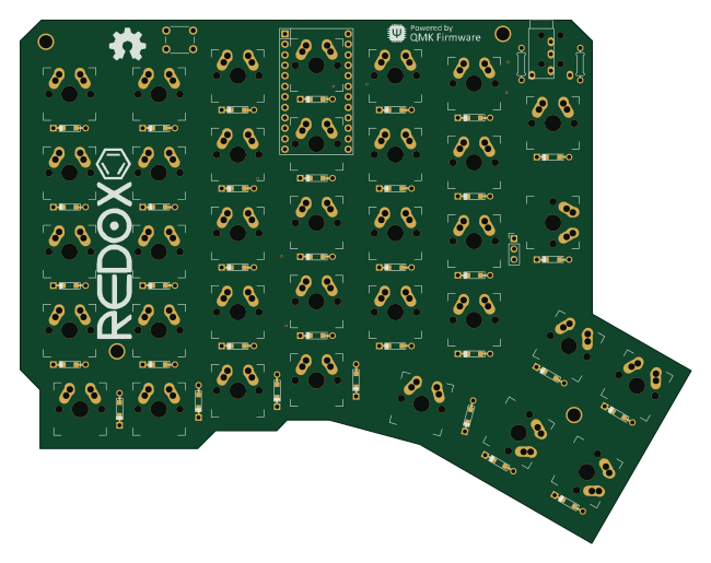 AVR/Arduino
Redox keyboard
mattdibi
162.2 × 126.5 mm77 parts2LMIT2.0k AVR/Arduino
Labrador
espotek-org
36.8 × 34.7 mm75 parts2LNo license1.2k AVR/Arduino
V4
stuartpittaway
30 × 50 mm38 parts2LCC-BY-NC-4.01.1k AVR/Arduino
ModuleV450
30 × 61.4 mm39 parts2LCC-BY-NC-4.01.1k AVR/Arduino
Discipline
coseyfannitutti
304.9 × 122.8 mm170 parts2LCC-BY-NC-4.01.0k