
Qn8035-rpi fm radio

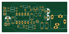
About the Qn8035-rpi fm radio PCB
Qn8035-rpi fm radio is an open source PCB design by dilshan, published on GitHub under the MIT license. It is a 2-layer board measuring 58 × 26.8 mm, with 25 components from 20 distinct parts.
Other key parts include the QN8035. By type, the board carries 11 capacitors, 7 resistors, 3 connectors, 1 IC, 1 transistor and 1 crystal.
It belongs with the rf & radio and audio designs in this gallery.
From the project
QN8035 based Raspberry Pi FM radio receiver
QN8035 is a single-chip stereo FM radio receiver IC designed by the Quintic Corporation. This receiver supports the FM broadcast band ranging from 60MHz to 108MHz.
This repository contains a Raspberry Pi base QN8035 receiver to receive FM stereo broadcasts from 88MHz to 108MHz.
The hardware part of this receiver consists of a QN8035 tuner and a 32.768kHz oscillator circuit. These circuits are designed to work with a 3.3V power supply.
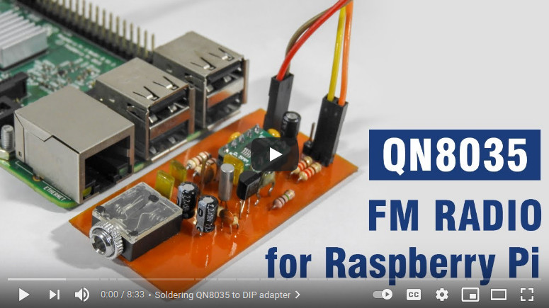
Main components on the Qn8035-rpi fm radio
Qn8035-rpi fm radio bill of materials (BOM)
25 components, 20 distinct parts — part numbers from the project's BOM.
| Qty | Part | Footprint | Refs |
|---|---|---|---|
| 1 | QN8035 | DIP-10_W7.62mm_LongPads | U1 |
| 1 | 2N3904 | TO-92_HandSolder | Q1 |
| 1 | 32.768kHz | Crystal_AT310_D3.0mm_L10.0mm_Vertical | Y1 |
| 1 | PJ324 | Jack_3.5mm_Ledino_KB3SPRS_Horizontal | J1 |
| 1 | 2x2.54mm | PinHeader_1x02_P2.54mm_Vertical | J2 |
| 1 | 3x2.54mm | PinHeader_1x03_P2.54mm_Vertical | J3 |
| 1 | Antenna | TestPoint_Loop_D2.50mm_Drill1.0mm | AE1 |
| 1 | 100PF 100pF | C_Disc_D3.0mm_W2.0mm_P2.50mm | C1 |
| 2 | 2.2MFD | CP_Radial_D5.0mm_P2.50mm | C2, C3 |
| 1 | 0.01MFD | C_Disc_D5.0mm_W2.5mm_P5.00mm | C4 |
| 2 | 0.001MFD | C_Disc_D5.0mm_W2.5mm_P5.00mm | C5, C6 |
| 1 | 10MFD | CP_Radial_D5.0mm_P2.50mm | C7 |
| 2 | 0.1MFD | C_Disc_D6.0mm_W2.5mm_P5.00mm | C8, C9 |
| 1 | 56PF 56pF | C_Disc_D5.1mm_W3.2mm_P5.00mm | C10 |
| 1 | 22PF 22pF | C_Disc_D3.0mm_W1.6mm_P2.50mm | C11 |
| 2 | 100R | R_Axial_DIN0204_L3.6mm_D1.6mm_P7.62mm_Horizontal | R1, R4 |
| 2 | 220R | R_Axial_DIN0204_L3.6mm_D1.6mm_P7.62mm_Horizontal | R2, R3 |
| 1 | 1M | R_Axial_DIN0204_L3.6mm_D1.6mm_P7.62mm_Horizontal | R5 |
| 1 | 0R | R_0805_2012Metric_Pad1.20x1.40mm_HandSolder | R6 |
| 1 | 10M | R_Axial_DIN0204_L3.6mm_D1.6mm_P7.62mm_Horizontal | R7 |
Qn8035-rpi fm radio design files
The KiCad project lives in the dilshan/qn8035-rpi-fm-radio repository on GitHub; these links point at the commit this page was built from.
Qn8035-rpi fm radio: common questions
How big is the Qn8035-rpi fm radio PCB?
The Qn8035-rpi fm radio measures 58 × 26.8 mm, has 2 copper layers and is 1.6 mm thick.
How many components are on the Qn8035-rpi fm radio?
25 components, from 20 distinct parts, with part numbers taken from the project's own BOM. The full bill of materials is listed on this page.
Where can I download the Qn8035-rpi fm radio design files?
From the dilshan/qn8035-rpi-fm-radio repository on GitHub, which has the KiCad layout and the BOM; the links under Design files point to each one.
Can I use the Qn8035-rpi fm radio design in my own project?
Yes, under the terms of its MIT license, which dilshan chose for the repository.
Similar boards
KLOR
GEIGEIGEIST
160.2 × 118.3 mm79 parts2LGPL-3.01.2k
ButtonsLEDs
shanteacontrols
390 × 37 mm82 parts2LApache-2.0956
USB
52 × 12.6 mm6 parts2LApache-2.0956
Pots
390 × 93 mm75 parts2LApache-2.0956
PicoGUS Hand386
polpo
29.2 × 75.2 mm43 parts4LGPL-2.0800
Snark barker
schlae
231.1 × 106.7 mm193 parts2LNo license687