
Duet3-ScanningZProbe

About the Duet3-ScanningZProbe PCB
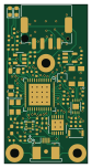
Duet3-ScanningZProbe is an open source Microchip SAM PCB design by Duet3D, published on GitHub. It is a 4-layer board measuring 20 × 38 mm, with 60 components from 35 distinct parts.
Its main chip is the ATSAMC21G18A, from the Microchip SAM family. Other key parts include the LDC1612, AP7366-W5-7, MCP2542, alternitivelty MCP2558, LIS2DW12 and LDK130M25R. By type, the board carries 21 capacitors, 20 resistors, 6 ICs, 3 jumpers, 3 diodes and 2 connectors.
From the project
The Duet 3 Scanning Z probe is a CAN-FD connected inductive sensing board, with compatible inductive PCB coils. It allows for a point mesh of the bed to be built up quickly as no movement in Z is required to read the bed distance, and individual readings happen very quickly.
Product Page: https://www.duet3d.com/Duet3ScanningZProbe
Main components on the Duet3-ScanningZProbe
Duet3-ScanningZProbe bill of materials (BOM)
60 components, 35 distinct parts.
| Qty | Part | Footprint | Refs |
|---|---|---|---|
| 1 | ATSAMC21G18A | QFN-48-1EP_7x7mm_P0.5mm_EP5.2x5.2mm_ThermalVias_thinpads | U1 |
| 1 | LDC1612 | WSON-12-1EP_4x4mm_P0.5mm_EP2.6x3mm_ThermalVias | U2 |
| 1 | AP7366-W5-7 (If AP7366-33W5-7 is used as an alternative DNP R45 and R46) AP7366-W5-7 | SOT-23-5 | U3 |
| 1 | MCP2542, alternitivelty MCP2558 MCP2542 | DFN-8-1EP_3x2mm_P0.5mm_EP1.3x1.5mm-thinpads | U4 |
| 1 | LIS2DW12 | LGA-12_2x2mm_P0.5mm | U5 |
| 1 | LDK130M25R | SOT-23-5 | U6 |
| 1 | TSX-3225 25.0000MF10P | Crystal_SMD_ECS-33B-4Pin_3.2x2.5mm | X1 |
| 1 | SM04B-PASS CAN & POWER | JST_PA_SM04B-PASS_1x04-1MP_P2.00mm_Horizontal | J2 |
| 1 | HDGC 0.5K-AX-4PWB Coil & Temp | FFC-4S-0.5SH_1x04-1MP_P0.50mm_Horizontal | J3 |
| 1 | virtual component - DNP CAN Termination | SolderJumper-2_P1.3mm_Open_TrianglePad1.0x1.5mm | JP1 |
| 1 | virtual component - DNP CANL/RX | SolderJumper-3_P1.3mm_Bridged12_RoundedPad1.0x1.5mm | JP3 |
| 1 | virtual component - DNP CANH/TX | SolderJumper-3_P1.3mm_Bridged12_RoundedPad1.0x1.5mm | JP4 |
| 1 | KXT 331 LHS CAN RESET | SW_SPST_CK_KXT3 | SW1 |
| 1 | virtual component - DNP PA27 | SolderJumper-2_P1.3mm_Open_TrianglePad1.0x1.5mm | TP6 |
| 1 | 150060RS75000 or equivalent Red STATUS | LED_0603_1608Metric | D1 |
| 1 | 150060VS75000 or equivalent Green ACT | LED_0603_1608Metric | D2 |
| 1 | BAT54CW,115 BAT54CW | SOT-323_SC-70 | D3 |
| 1 | BKP1005HS221-T Ferrite Bead | L_0402_1005Metric | L1 |
| 1 | 744235110 CM Choke | Wurth_CM_Choke_1812_744235nnn | L2 |
| 2 | C0402C220J4GACTU 22p 16V 5% C0G,NP0 | C_0402_1005Metric_Wbry | C1, C2 |
Show 15 more
| Qty | Part | Footprint | Refs |
|---|---|---|---|
| 2 | CL21B106KPQNNNG 10u 10V 10% X7R | C_0805_2012Metric | C3, C10 |
| 6 | GRM155Z71A105KE01D 1u 10V 10% X7R | C_0402_1005Metric_Wbry | C4, C12, C14, C15, C17, C21 |
| 9 | CL05B104KP5NNNC 0u1 10V 10% X7R | C_0402_1005Metric_Wbry | C5, C6, C7, C8, C9, C11, C18, C20 +1 |
| 2 | CC0402KRX7R6BB103 10n 10V 10% X7R | C_0402_1005Metric_Wbry | C13, C16 |
| 2 | RMCF0402FT1K00 1K 1% 0.063W | R_0402_1005Metric_Wbry | R1, R10 |
| 4 | RK73H1ETTP1002F 10K 1% 0.1W | R_0402_1005Metric_Wbry | R2, R8, R15, R23 |
| 4 | RMCF0402FT4K70 4K7 1% 0.063W | R_0402_1005Metric_Wbry | R3, R9, R11, R16 |
| 1 | RMCF0402FT180R 180R 1% 0.063W | R_0402_1005Metric_Wbry | R4 |
| 2 | RMCF0402FT2K40 2K4 1% 0.063W | R_0402_1005Metric_Wbry | R6, R20 |
| 2 | RMCF0402FT100K 100K 1% 0.063W | R_0402_1005Metric_Wbry | R7, R17 |
| 1 | ERJ-2RKF2202X 22K 1% 0.1W | R_0402_1005Metric_Wbry | R14 |
| 1 | ERJ-PB3B2201V 2K2 0.1% 0.2W | R_0603_1608Metric_Wbry | R18 |
| 1 | RMCF0402FT7K50 7K5 1% 0.063W | R_0402_1005Metric_Wbry | R19 |
| 1 | RMCF0402FT120R 120R 1% 0.063W | R_0402_1005Metric_Wbry | R21 |
| 1 | RC0402FR-07470RL 470R 1% 0.063W | R_0402_1005Metric_Wbry | R22 |
Duet3-ScanningZProbe design files
The KiCad project lives in the Duet3D/Duet3-ScanningZProbe repository on GitHub; these links point at the commit this page was built from.
- Layoutv1.0/Duet3_SZP.kicad_pcb
- Schematicv1.0/Duet3_SZP.kicad_sch
Duet3-ScanningZProbe: common questions
What microcontroller does the Duet3-ScanningZProbe use?
The Duet3-ScanningZProbe is built around the ATSAMC21G18A, from the Microchip SAM family.
How big is the Duet3-ScanningZProbe PCB?
The Duet3-ScanningZProbe measures 20 × 38 mm, has 4 copper layers and is 1.6 mm thick.
How many components are on the Duet3-ScanningZProbe?
60 components, from 35 distinct parts. The full bill of materials is listed on this page.
Where can I download the Duet3-ScanningZProbe design files?
From the Duet3D/Duet3-ScanningZProbe repository on GitHub, which has the KiCad layout and the schematic; the links under Design files point to each one.
Can I use the Duet3-ScanningZProbe design in my own project?
The repository has no license, so all rights stay with Duet3D. Use it as a reference, and ask the author before reusing the design.
Can I test firmware for the Duet3-ScanningZProbe without the hardware?
Yes. HardLabs builds a simulation of the board from its netlist and BOM, so you can run and debug Microchip SAM firmware against it before you order a PCB.
Similar boards
 Microchip SAM
Microcontroller Expansion Card
FrameworkComputer
26 × 30 mm24 parts2LCC-BY-4.01.1k Microchip SAM
Taco Raven
VoronDesign
120 × 113 mm349 parts4LGPL-3.01.1k Microchip SAM
Fpgaboy
Wren6991
50 × 50 mm89 parts4LNo license508 Microchip SAM
OpenDropV4
GaudiLabs
124 × 115.4 mm118 parts2LGPL-3.0487 Microchip SAM
ModulAdapter universal
100 × 69.5 mm45 parts2LGPL-3.0487 Microchip SAM
Kira
kiibohd
366.9 × 114.3 mm400 partsCERN-OHL-1.2415