
TimeReceiver225kHz

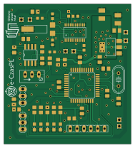
About the TimeReceiver225kHz PCB
TimeReceiver225kHz is an open source PIC PCB design by e-CzasPL, published on GitHub under the MIT license. It is a 2-layer board measuring 47 × 52 mm, with 56 components from 29 distinct parts.
Its main chip is the DSPIC33FJ64MC804-PT, from the PIC family. Other key parts include the MCP607SO8, LM1117 and SI4735-D60. By type, the board carries 20 capacitors, 14 resistors, 5 LEDs, 4 ICs, 1 transistor and 1 crystal.
From the project
A simple receiver module for decoding a time frame from a 225kHz transmitter in Solec Kujawski, Poland
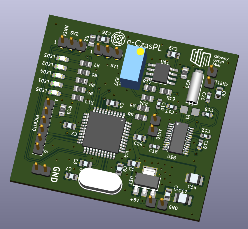
Main components on the TimeReceiver225kHz
TimeReceiver225kHz bill of materials (BOM)
56 components, 29 distinct parts — part numbers from the project's BOM.
| Qty | Part | Footprint | Refs |
|---|---|---|---|
| 1 | DSPIC33FJ64MC804-PT | TQFP44 | IC4 |
| 1 | MCP607SO8 | SOIC8 | U$1 |
| 1 | LM1117 | SOT223-3 | U$3 |
| 1 | SI4735-D60 | SSOP24 | U$5 |
| 1 | 10MHZ 10MHz | HC49U-V | Q1 |
| 1 | CMR309T | CMR309T | Y1 |
| 1 | 1,6/0,9 | 1,6_0,9 | ANT0 |
| 7 | 1,6/0,9 | 1,6_0,9 | PAD1, PAD2, PAD3, PAD6, PAD7, PAD8, PAD9 |
| 1 | FE06-1 | FE06 | PICKIT0 |
| 2 | MA03-1 | MA03-1 | SV1, SV2 |
| 5 | LEDCHIP-LED0805 | CHIP-LED0805 | LED1, LED2, LED3, LED4, LED5 |
| 1 | 1n | C0805K | C1 |
| 7 | 100N 100n | C0805K | C2, C3, C5, C8, C24, C26, C29 |
| 1 | 4U7 4u7 | C0805K | C4 |
| 2 | 27P 27p | C0805K | C7, C9 |
| 2 | 4U7 4u7 | C0603K | C10, C21 |
| 1 | 22N 22n | C0603K | C12 |
| 2 | 22P 22p | C0603K | C13, C15 |
| 1 | 10U 10u | SMC_B | C14 |
| 1 | 220U 220u | SMC_B | C17 |
Show 9 more
| Qty | Part | Footprint | Refs |
|---|---|---|---|
| 1 | 470N 470n | C0603K | C18 |
| 1 | 100N 100n | C0603K | C19 |
| 5 | 470 | R0805 | R1, R6, R7, R8, R13 |
| 1 | 20K 20k | R0805 | R2 |
| 2 | 4K7 4k7 | R0805 | R5, R9 |
| 3 | 470K 470k | M0805 | R17, R19, R20 |
| 1 | 10K 10k | R0805 | R18 |
| 1 | 18K 18k | M0805 | R24 |
| 1 | 200K 200k | RJ9W | R27 |
TimeReceiver225kHz design files
The KiCad project lives in the e-CzasPL/TimeReceiver225kHz repository on GitHub; these links point at the commit this page was built from.
TimeReceiver225kHz: common questions
What microcontroller does the TimeReceiver225kHz use?
The TimeReceiver225kHz is built around the DSPIC33FJ64MC804-PT, from the PIC family.
How big is the TimeReceiver225kHz PCB?
The TimeReceiver225kHz measures 47 × 52 mm, has 2 copper layers and is 1.6 mm thick.
How many components are on the TimeReceiver225kHz?
56 components, from 29 distinct parts, with part numbers taken from the project's own BOM. The full bill of materials is listed on this page.
Where can I download the TimeReceiver225kHz design files?
From the e-CzasPL/TimeReceiver225kHz repository on GitHub, which has the KiCad layout, the schematic and the BOM; the links under Design files point to each one.
Can I use the TimeReceiver225kHz design in my own project?
Yes, under the terms of its MIT license, which e-CzasPL chose for the repository.
Can I test firmware for the TimeReceiver225kHz without the hardware?
Yes. HardLabs builds a simulation of the board from its netlist and BOM, so you can run and debug PIC firmware against it before you order a PCB.
Similar boards
 PIC
PICPslab hardware
fossasia
99 × 53.3 mm187 parts4LApache-2.01.7k PIC
PICGB-MBCTEST
Gekkio
51.4 × 61 mm32 parts2LCC-BY-4.0376 PIC
PICGB-CARTPP-DIY
100 × 100 mm22 parts2LCC-BY-4.0376 PIC
PICGB-LIVE32
51.4 × 61 mm46 parts4LCC-BY-4.0376 PIC
PICGB-BENCH-G1
100 × 100 mm98 parts4LCC-BY-4.0376 PIC
PICGB-CARTPP-XC
80 × 55 mm19 parts2LCC-BY-4.0376