
Bms monitor

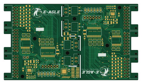
About the Bms monitor PCB
Bms monitor is an open source PCB design by eagletrt, published on GitHub under the Custom license license. It is a 2-layer board measuring 115 × 65 mm, with 215 components from 44 distinct parts.
Other key parts include the LTC6811-1, 74HC4067PW,118 and SM91502ALA. By type, the board carries 48 resistors, 32 capacitors, 26 connectors, 16 jumpers, 13 fuses and 8 ICs.
It belongs with the power & battery designs in this gallery.
From the project
Slave BMS module to monitor 24s cells voltages and temperatures.
Slave BMS module to monitor 24s cells voltages and temperatures.
- 24 cells series - 32 temperature measurements - LTC6811-1/-2 both are compatible - isoSPI cost effective communication interface to the monitor IC directly - cell balancing - STM32L0 can be fitted to add logic to the board by itself - IRda optional communication to the MCU - compatible, for temperatures, with both NTC and shunt references - direct SPI connection to the monitor ICs - usable as two 12S monitor with breakaway slots - cost reduction in the isolation components if used as 24S monitor - small footprint, 65mmx115mm
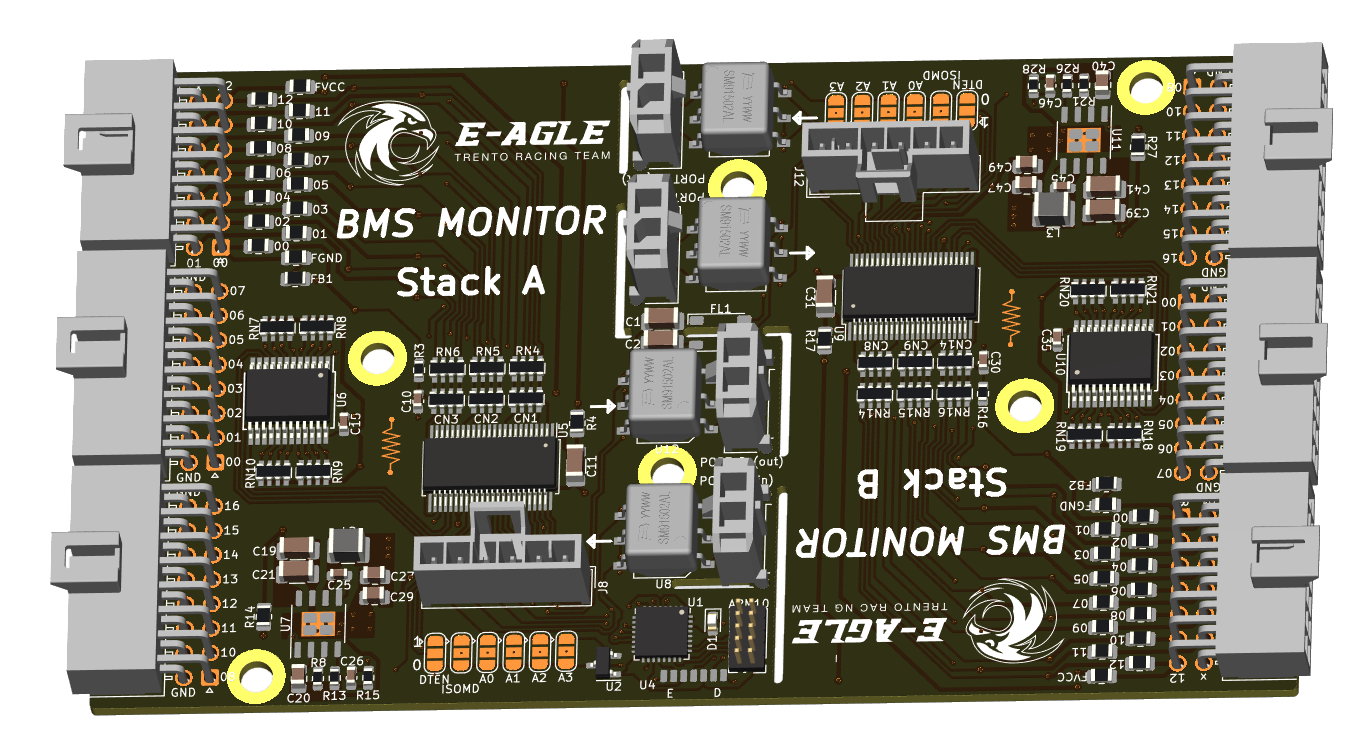
Main components on the Bms monitor
Bms monitor bill of materials (BOM)
215 components, 44 distinct parts.
| Qty | Part | Footprint | Refs |
|---|---|---|---|
| 2 | LTC6811-1 | SSOP-48_5.3x12.8mm_P0.5mm | U5, U9 |
| 2 | 74HC4067PW,118 | SSOP-24_5.3x8.2mm_P0.65mm | U6, U10 |
| 4 | SM91502ALA | SM91502ALA | U8, U12, U13, U14 |
| 2 | NSS1C201MZ4 | SOT-223 | Q1, Q2 |
| 6 | 10nF | R_Array_Convex_4x0603 | CN1, CN2, CN3, CN8, CN9, CN14 |
| 8 | 100nF | R_Array_Convex_4x0603 | CN4, CN5, CN6, CN7, CN10, CN11, CN12, CN13 |
| 4 | Conn_01x02 | Molex_Micro-Fit_3.0_43650-0215_1x02_P3.00mm_Vertical | J1, J2, J3, J4 |
| 2 | CELLS | Molex_Nano-Fit_105314-xx14_2x07_P2.50mm_Horizontal | J5, J9 |
| 2 | TEMP0 | Molex_Nano-Fit_105314-xx16_2x08_P2.50mm_Horizontal | J6, J10 |
| 2 | TEMP1 | Molex_Nano-Fit_105314-xx16_2x08_P2.50mm_Horizontal | J7, J11 |
| 2 | Conn_01x05 | Molex_Nano-Fit_105309-xx06_1x06_P2.50mm_Vertical | J8, J12 |
| 13 | 2A | Fuse_1206_3216Metric | F13, F14, F15, F16, F17, F18, F19, F20 +5 |
| 1 | ACT45B-101-2P-TL003 | ACT45B-xxx-2P-TL003 | FL1 |
| 15 | 2A | Fuse_1206_3216Metric | Fa0, Fa1, Fa2, Fa3, Fa4, Fa5, Fa6, Fa7 +7 |
| 2 | A0 | SolderJumper-3_P1.3mm_Open_RoundedPad1.0x1.5mm | JP1, JP7 |
| 2 | A1 | SolderJumper-3_P1.3mm_Open_RoundedPad1.0x1.5mm | JP2, JP8 |
| 2 | A2 | SolderJumper-3_P1.3mm_Open_RoundedPad1.0x1.5mm | JP3, JP9 |
| 2 | A3 | SolderJumper-3_P1.3mm_Open_RoundedPad1.0x1.5mm | JP4, JP10 |
| 2 | DTEN | SolderJumper-3_P1.3mm_Open_RoundedPad1.0x1.5mm | JP5, JP11 |
| 2 | ISOMD | SolderJumper-3_P1.3mm_Open_RoundedPad1.0x1.5mm | JP6, JP12 |
Show 24 more
| Qty | Part | Footprint | Refs |
|---|---|---|---|
| 2 | IBIAS | SolderJumper-3_P1.3mm_Open_RoundedPad1.0x1.5mm | JP13, JP15 |
| 2 | ICMP | SolderJumper-3_P1.3mm_Open_RoundedPad1.0x1.5mm | JP14, JP16 |
| 24 | BSS308PE | TSOT-23 | Qda0, Qda1, Qda2, Qda3, Qda4, Qda5, Qda6, Qda7 +16 |
| 24 | 10R | R_2512_6332Metric | Rda0, Rda1, Rda2, Rda3, Rda4, Rda5, Rda6, Rda7 +16 |
| 2 | LED_Small | LED_0603_1608Metric | D2, D3 |
| 2 | 600R | R_0805_2012Metric | FB1, FB2 |
| 2 | 2A | Fuse_1206_3216Metric | Fb3, Fb14 |
| 2 | 10nF 100V | C_1210_3225Metric | C1, C2 |
| 10 | 10nF | C_0603_1608Metric | C10, C17, C18, C22, C23, C30, C37, C38 +2 |
| 2 | 100nF 100V | C_1210_3225Metric | C11, C31 |
| 6 | 1uF | C_0805_2012Metric | C12, C13, C14, C32, C33, C34 |
| 2 | 100nF | C_0603_1608Metric | C15, C35 |
| 2 | F | C_0603_1608Metric | C16, C36 |
| 4 | 1uF 100V | C_1206_3216Metric | C19, C21, C39, C41 |
| 4 | 10uF | C_0805_2012Metric | C27, C29, C47, C49 |
| 6 | 100R | R_0805_2012Metric | R3, R4, R14, R16, R17, R27 |
| 6 | R | R_0603_1608Metric | R5, R6, R7, R18, R19, R20 |
| 8 | 51R | R_0603_1608Metric | R9, R10, R11, R12, R22, R23, R24, R25 |
| 4 | 100 | R_0603_1608Metric | R30, R31, R32, R33 |
| 2 | 1K | R_0603_1608Metric | R34, R35 |
| 6 | 3.3K | R_Array_Convex_4x0603 | RN1, RN2, RN3, RN11, RN12, RN13 |
| 6 | 100R | R_Array_Convex_4x0603 | RN4, RN5, RN6, RN14, RN15, RN16 |
| 8 | 27K | R_Array_Convex_4x0603 | RN7, RN8, RN9, RN10, RN18, RN19, RN20, RN21 |
| 2 | 10K | R_Array_Convex_4x0603 | RN17, RN22 |
Bms monitor design files
The KiCad project lives in the eagletrt/bms-monitor repository on GitHub; these links point at the commit this page was built from.
- Layoutbms_monitor.kicad_pcb
- Schematicbms_monitor.kicad_sch
Bms monitor: common questions
How big is the Bms monitor PCB?
The Bms monitor measures 115 × 65 mm, has 2 copper layers and is 1.6 mm thick.
How many components are on the Bms monitor?
215 components, from 44 distinct parts. The full bill of materials is listed on this page.
Where can I download the Bms monitor design files?
From the eagletrt/bms-monitor repository on GitHub, which has the KiCad layout and the schematic; the links under Design files point to each one.
Can I use the Bms monitor design in my own project?
It is published under Custom license, which limits how it may be reused; read the license before building on it.
Similar boards

EinkPDA screen
TalismanDesign
95 × 54 mm27 parts2LApache-2.02.0k
Stack chan
stack-chan
50 × 50 mm33 parts2LApache-2.01.7k
Display Carrier
AxxAxx
35.6 × 58.2 mm5 parts2LGPL-3.01.7k
ProgrammingAdapter
stuartpittaway
10.5 × 83 mm3 parts2LCC-BY-NC-4.01.1k
TemperaturePCB PANEL
116 × 75.5 mm178 parts2LCC-BY-NC-4.01.1k
Module 16S PassiveBalanceAddOn
61 × 74 mm86 parts2LCC-BY-NC-4.01.1k