
4-Stage-BJT-Amplifier

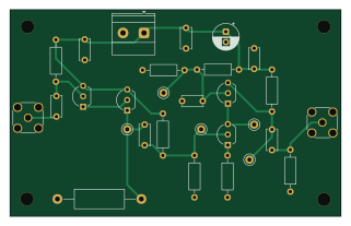
About the 4-Stage-BJT-Amplifier PCB
4-Stage-BJT-Amplifier is an open source PCB design by eblair363, published on GitHub. It is a 2-layer board measuring 80 × 50 mm, with 29 components from 14 distinct parts.
By type, the board carries 9 resistors, 8 capacitors, 5 test points, 4 transistors and 3 connectors.
It belongs with the audio designs in this gallery.
From the project
A discrete BJT amplifier — Darlington emitter follower into a cascode gain stage, four PN2222A transistors on a +24 V supply — originally designed in PSpice for a course, then re-implemented as a KiCad PCB. The first physical build was dead-bug on copper clad and it died on test
A discrete BJT amplifier — Darlington emitter follower into a cascode gain stage, four PN2222A transistors on a +24 V supply — originally designed in PSpice for a course, then re-implemented as a KiCad PCB. The first physical build was dead-bug on copper clad and it died on test day from an under-rated resistor. This repo is the rebuild: the same circuit, with the failure understood, the bias problem found in simulation before ordering, and the whole thing laid out on a proper board. The board and parts are ordered; nothing is assembled or measured yet, so every number here is simulated and…
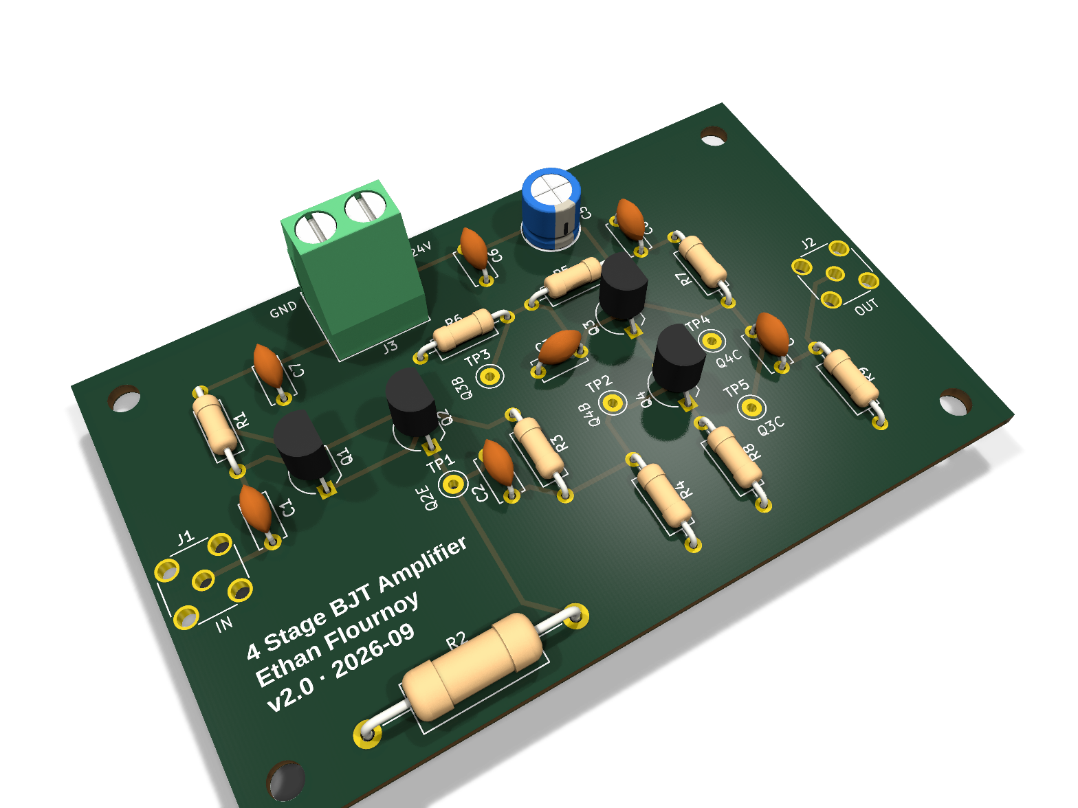
4-Stage-BJT-Amplifier bill of materials (BOM)
29 components, 14 distinct parts — part numbers from the project's BOM.
| Qty | Part | Footprint | Refs |
|---|---|---|---|
| 4 | PN2222A | TO-92_Inline_Wide | Q1, Q2, Q3, Q4 |
| 2 | SMA | SMA_Amphenol_132134_Vertical | J1, J2 |
| 1 | Screw_Terminal_01x02 | TerminalBlock_Phoenix_MKDS-1,5-2-5.08_1x02_P5.08mm_Horizontal | J3 |
| 5 | TestPoint | TestPoint_Keystone_5000-5004_Miniature | TP1, TP2, TP3, TP4, TP5 |
| 7 | 100nF 50V | C_Disc_D5.0mm_W2.5mm_P5.00mm | C1, C2, C3, C4, C6, C7, C8 |
| 1 | 10uF 50V | CP_Radial_D6.3mm_P2.50mm | C5 |
| 1 | 1M 1/4W | R_Axial_DIN0207_L6.3mm_D2.5mm_P10.16mm_Horizontal | R1 |
| 1 | 910 2W | R_Axial_DIN0414_L11.9mm_D4.5mm_P20.32mm_Horizontal | R2 |
| 1 | 10k 1/4W | R_Axial_DIN0207_L6.3mm_D2.5mm_P10.16mm_Horizontal | R3 |
| 1 | 360 1/4W | R_Axial_DIN0207_L6.3mm_D2.5mm_P10.16mm_Horizontal | R4 |
| 1 | 100k 1/4W | R_Axial_DIN0207_L6.3mm_D2.5mm_P10.16mm_Horizontal | R5 |
| 1 | 22k 1/4W | R_Axial_DIN0207_L6.3mm_D2.5mm_P10.16mm_Horizontal | R6 |
| 2 | 1k 1/4W | R_Axial_DIN0207_L6.3mm_D2.5mm_P10.16mm_Horizontal | R7, R9 |
| 1 | 10 1/4W | R_Axial_DIN0207_L6.3mm_D2.5mm_P10.16mm_Horizontal | R8 |
4-Stage-BJT-Amplifier design files
The KiCad project lives in the eblair363/4-Stage-BJT-Amplifier repository on GitHub; these links point at the commit this page was built from.
4-Stage-BJT-Amplifier: common questions
How big is the 4-Stage-BJT-Amplifier PCB?
The 4-Stage-BJT-Amplifier measures 80 × 50 mm, has 2 copper layers and is 1.6 mm thick.
How many components are on the 4-Stage-BJT-Amplifier?
29 components, from 14 distinct parts, with part numbers taken from the project's own BOM. The full bill of materials is listed on this page.
Where can I download the 4-Stage-BJT-Amplifier design files?
From the eblair363/4-Stage-BJT-Amplifier repository on GitHub, which has the KiCad layout, the schematic and the BOM; the links under Design files point to each one.
Can I use the 4-Stage-BJT-Amplifier design in my own project?
The repository has no license, so all rights stay with eblair363. Use it as a reference, and ask the author before reusing the design.
Similar boards
KLOR
GEIGEIGEIST
160.2 × 118.3 mm79 parts2LGPL-3.01.2k
ButtonsLEDs
shanteacontrols
390 × 37 mm82 parts2LApache-2.0956
USB
52 × 12.6 mm6 parts2LApache-2.0956
Pots
390 × 93 mm75 parts2LApache-2.0956
PicoGUS Hand386
polpo
29.2 × 75.2 mm43 parts4LGPL-2.0800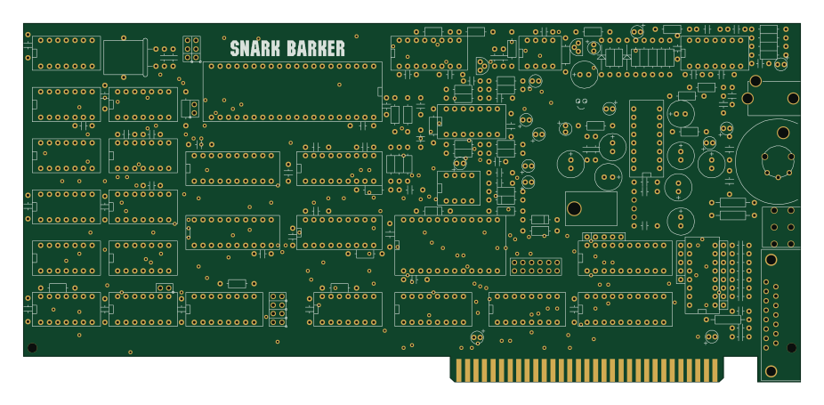
Snark barker
schlae
231.1 × 106.7 mm193 parts2LNo license687