
915MHzEdisonExplorer

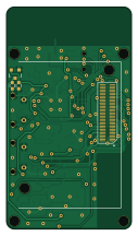
About the 915MHzEdisonExplorer PCB
915MHzEdisonExplorer is an open source PCB design by EnhancedRadioDevices, published on GitHub. It is a 2-layer board measuring 30.5 × 53.9 mm, with 76 components from 44 distinct parts.
Other key parts include the H124603, MCP73831T-2ATI/OT, 296-38889-1, 296-27217-1 and 712-1541-1. By type, the board carries 30 capacitors, 21 resistors, 10 ICs, 5 diodes, 3 connectors and 2 modules.
It belongs with the rf & radio and iot & wireless designs in this gallery.
From the project
A 915MHz block for the Intel Edison.
This Edison Block makes use of a TI CC1110 RF transciever to allow a connected Edison to communicate on the 915MHz band. It is also capable of transmitting at 868MHz (a small antenna alteration will make it much more efficient at that band).
The 915MHz Edison Explorer Block allows an Intel Edison to serve as a bridge from WiFi or Bluetooth to a 915MHz protocol, such as Z-wave, Zigbee, or other manufacturer specific protocols.
Main components on the 915MHzEdisonExplorer
915MHzEdisonExplorer bill of materials (BOM)
76 components, 44 distinct parts — part numbers from the project's BOM.
| Qty | Part | Footprint | Refs |
|---|---|---|---|
| 1 | H124603 EdisonConnector | DF40HC(3.0)-70DS | U1 |
| 1 | DNP | SOT-23 | U2 |
| 1 | MCP73831T-2ATI/OT MCP73831 | SOT-23-5 | U3 |
| 1 | 296-38889-1 CC1110 | QFN-36-1EP_6x6mm_Pitch0.5mm | U4 |
| 1 | 296-27217-1 TXB0108-DFN20 | UFDFN-20_4x2mm_Pitch0.4mm | U5 |
| 1 | 712-1541-1 0915BM15A0001 | 0915BM15A0001 | U6 |
| 1 | AP7365-39WG-7DI AP7365 | SOT-23-5 | U7 |
| 1 | 576-4145-1 MIC2039AY | SOT-23-6 | U8 |
| 1 | 296-27373-1 TPS2113A | SON-8 | U9 |
| 1 | 768-1130-1 FT230X | QFN-16-1EP_4x4mm_Pitch0.65mm | U10 |
| 1 | 712-1535-1 0915AT43A0026E | ANT_SMD_0868AT43A0020E_labeled | A1 |
| 1 | A118077 TE_1909763-1 | MiniRFHeader | A2 |
| 1 | 887-2580-1 24MHz | Crystal_4-SMD_TXC-7V | X1 |
| 1 | 609-3695-1 DNP | M05x2_FTSH_MTR | P1 |
| 2 | 609-4618-1 Amphenol 10118194-0001LF | USB_Micro-B | P6, P7 |
| 1 | 455-1749-1 M02JST-PTH-2 | JST_PH_S2B-PH-SM4-TB_02x2.00mm_Angled | JP1 |
| 1 | SW1020 B3U-1000P | SW_SPST_B3U-1000P | SW1 |
| 3 | 160-1436-1 RED | LED_0603 | D1, D2, D6 |
| 1 | 160-1446-2 GREEN | LED_0603 | D3 |
| 1 | DNP | SOD-323 | D5 |
Show 24 more
| Qty | Part | Footprint | Refs |
|---|---|---|---|
| 1 | 490-1162-1 4.7n | C_0603 | L6 |
| 1 | 490-1169-1 10n | C_0603 | L7 |
| 9 | 1276-1045-6 4.7u | C_0603 | C1, C2, C13, C15, C16, C24, C26, C29 +1 |
| 1 | 490-3890-1 1u | C_0402 | C3 |
| 8 | 490-6328-1 0.1u | C_0402 | C4, C5, C11, C12, C19, C20, C21, C25 |
| 2 | 490-4516-1 10n | C_0402 | C6, C8 |
| 1 | 490-5932-1 2p2 | C_0402 | C7 |
| 1 | 490-1293-1 220p | C_0402 | C9 |
| 2 | 490-5858-1 18p | C_0402 | C10, C14 |
| 1 | 720-1325-1 100p | C_0603 | C17 |
| 1 | 1276-1818-1 0.5p | C_0603 | C18 |
| 2 | 490-6241-1 47p | C_0402 | C22, C23 |
| 2 | DNP | C_0603 | C27, C28 |
| 4 | 311-330JR 330 | R_0402 | R1, R9, R10, R11 |
| 1 | 311-2.0KJR 4k | R_0402 | R2 |
| 2 | DNP | R_0402 | R3, R4 |
| 1 | 311-56KJR 56k | R_0402 | R5 |
| 2 | YAG3089 287 | R_0402 | R6, R13 |
| 4 | 311-10KJR 10k | R_0402 | R7, R8, R15, R20 |
| 1 | YAG3215 698 | R_0402 | R12 |
| 1 | 311-100KLR 100k | R_0402 | R14 |
| 2 | 311-100LR 100 | R_0402 | R16, R17 |
| 2 | 311-27JR 27 | R_0402 | R18, R19 |
| 1 | 311-3.0KJR 3k | R_0402 | R21 |
915MHzEdisonExplorer design files
The KiCad project lives in the EnhancedRadioDevices/915MHzEdisonExplorer repository on GitHub; these links point at the commit this page was built from.
915MHzEdisonExplorer: common questions
How big is the 915MHzEdisonExplorer PCB?
The 915MHzEdisonExplorer measures 30.5 × 53.9 mm, has 2 copper layers and is 0.8 mm thick.
How many components are on the 915MHzEdisonExplorer?
76 components, from 44 distinct parts, with part numbers taken from the project's own BOM. The full bill of materials is listed on this page.
Where can I download the 915MHzEdisonExplorer design files?
From the EnhancedRadioDevices/915MHzEdisonExplorer repository on GitHub, which has the KiCad layout and the BOM; the links under Design files point to each one.
Can I use the 915MHzEdisonExplorer design in my own project?
The repository has no license, so all rights stay with EnhancedRadioDevices. Use it as a reference, and ask the author before reusing the design.
Similar boards
EinkPDA screen
TalismanDesign
95 × 54 mm27 parts2LApache-2.02.0k
RPi RM0 WiFi/Bluetooth Module
schlae
11.1 × 14 mm76 parts6LNo license1.0k
Radioberry juice
pa3gsb
65 × 56 mm87 parts2LNo license675
Radioberry preamp
65 × 56 mm137 parts2LNo license675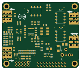
Hat
65 × 56 mm81 parts2LNo license675
Goodwatch31
travisgoodspeed
25.6 × 27.6 mm23 parts2LNo license568