
137mhz lrpt receiver

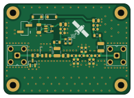
About the 137mhz lrpt receiver PCB
137mhz lrpt receiver is an open source PCB design by ernesto-ramirez-ee, published on GitHub. It is a 2-layer board measuring 48.7 × 35 mm, with 33 components from 20 distinct parts.
Other key parts include the PGA-103 and TLV75733PDBV. By type, the board carries 16 capacitors, 7 inductors, 4 diodes, 3 connectors, 2 ICs and 1 resistor.
It belongs with the rf & radio designs in this gallery.
From the project
VHF receiver front end and Python LRPT decoder for the Meteor-M2 weather satellite (137.9 MHz, QPSK, 72 ksym/s).
VHF receiver front end and Python LRPT decoder for the Meteor-M2 weather satellite (137.9 MHz, QPSK, 72 ksym/s).
2-layer, ~49 × 35 mm front-end board designed in KiCad. Signal path:
- LNA: Mini-Circuits PGA-103+, powered at 3.3 V from a TLV75733P LDO. - Filter: 3-pole direct-coupled Chebyshev bandpass, 130–145 MHz, 0.1 dB ripple, series-capacitor coupling with shunt LC resonators. - Power: 2-pin header or bias tee on either SMA port (Schottky OR-ing into the LDO).

Main components on the 137mhz lrpt receiver
137mhz lrpt receiver bill of materials (BOM)
33 components, 20 distinct parts — part numbers from the project's BOM.
| Qty | Part | Footprint | Refs |
|---|---|---|---|
| 1 | PGA-103 | SOT-89-3 | U1 |
| 1 | TLV75733PDBV | SOT-23-5 | U2 |
| 2 | C496551 Conn_Coaxial | SMA_BAT_Wireless_BWSMA-KWE-Z001 | J1, J2 |
| 1 | CONN_01X02_PIN Conn_01x02_Pin | PinHeader_1x02_P2.54mm_Vertical_SMD_Pin1Right | J3 |
| 1 | BAV99 | SOT-23 | D1 |
| 2 | C7502706 D_Schottky | D_SOD-123 | D2, D3 |
| 1 | LED | LED_0603_1608Metric | D4 |
| 3 | 22NH 22nH | L_0603_1608Metric | L1, L2, L3 |
| 2 | 390NH 390nH | L_1210_3225Metric | L5, L7 |
| 2 | 2.2UH 2.2uH | L_0805_2012Metric | L6, L8 |
| 2 | 2.2NF 2.2nF | C_0805_2012Metric | C1, C2 |
| 2 | 22PF 22pF | C_0603_1608Metric | C3, C6 |
| 2 | 10PF 10pF | C_0603_1608Metric | C4, C5 |
| 2 | 39PF 39pF | C_0603_1608Metric | C8, C10 |
| 1 | 43PF 43pF | C_0603_1608Metric | C9 |
| 2 | 100PF 100pF | C_0603_1608Metric | C12, C15 |
| 2 | 1UF 1uF | C_0805_2012Metric | C13, C14 |
| 1 | 10UF 10uF | C_1206_3216Metric | C16 |
| 2 | 10NF 10nF | C_0603_1608Metric | C17, C18 |
| 1 | 680 | R_0603_1608Metric | R1 |
137mhz lrpt receiver design files
The KiCad project lives in the ernesto-ramirez-ee/137mhz-lrpt-receiver repository on GitHub; these links point at the commit this page was built from.
137mhz lrpt receiver: common questions
How big is the 137mhz lrpt receiver PCB?
The 137mhz lrpt receiver measures 48.7 × 35 mm, has 2 copper layers and is 1.6 mm thick.
How many components are on the 137mhz lrpt receiver?
33 components, from 20 distinct parts, with part numbers taken from the project's own BOM. The full bill of materials is listed on this page.
Where can I download the 137mhz lrpt receiver design files?
From the ernesto-ramirez-ee/137mhz-lrpt-receiver repository on GitHub, which has the KiCad layout, the schematic and the BOM; the links under Design files point to each one.
Can I use the 137mhz lrpt receiver design in my own project?
The repository has no license, so all rights stay with ernesto-ramirez-ee. Use it as a reference, and ask the author before reusing the design.
Similar boards
Hat
pa3gsb
65 × 56 mm81 parts2LNo license675
Radioberry juice
65 × 56 mm87 parts2LNo license675
Radioberry preamp
65 × 56 mm137 parts2LNo license675
Goodwatch20
travisgoodspeed
25.6 × 27.6 mm20 parts2LNo license568
GoodPocketWatch
75.2 × 101.2 mm56 parts2LNo license568
Goodwatch31
25.6 × 27.6 mm23 parts2LNo license568