
Usb to serial append


About the Usb to serial append PCB
Usb to serial append is an open source PCB design by ExploreEmbedded, published on GitHub. It is a board measuring 33.5 × 2.8 mm, with 7 components from 7 distinct parts.
Other key parts include the CP2102. By type, the board carries 2 connectors, 2 capacitors, 1 IC, 1 diode and 1 resistor.
It belongs with the usb & debug tools designs in this gallery.
From the project
Pic16f877a Design files and sample code for Ultra Development Kit
Main components on the Usb to serial append
Usb to serial append bill of materials (BOM)
7 components, 7 distinct parts — part numbers from the project's BOM.
| Qty | Part | Footprint | Refs |
|---|---|---|---|
| 1 | CP2102 | cp2102_xl2 | U1 |
| 1 | USB_2 | USB_B | J1 |
| 1 | CONN_7 | SIL-7 | P1 |
| 1 | LED | SM1206 | D1 |
| 1 | 0.1uF | SM1206 | C2 |
| 1 | 1uF | SM1206 | C3 |
| 1 | 330r | SM1206 | R1 |
Usb to serial append design files
The KiCad project lives in the ExploreEmbedded/Pic16f877a_ExploreUltraPicDevKit repository on GitHub; these links point at the commit this page was built from.
Usb to serial append: common questions
How big is the Usb to serial append PCB?
The Usb to serial append measures 33.5 × 2.8 mm and is 1.6002 mm thick.
How many components are on the Usb to serial append?
7 components, from 7 distinct parts, with part numbers taken from the project's own BOM. The full bill of materials is listed on this page.
Where can I download the Usb to serial append design files?
From the ExploreEmbedded/Pic16f877a_ExploreUltraPicDevKit repository on GitHub, which has the KiCad layout and the BOM; the links under Design files point to each one.
Can I use the Usb to serial append design in my own project?
The repository has no license, so all rights stay with ExploreEmbedded. Use it as a reference, and ask the author before reusing the design.
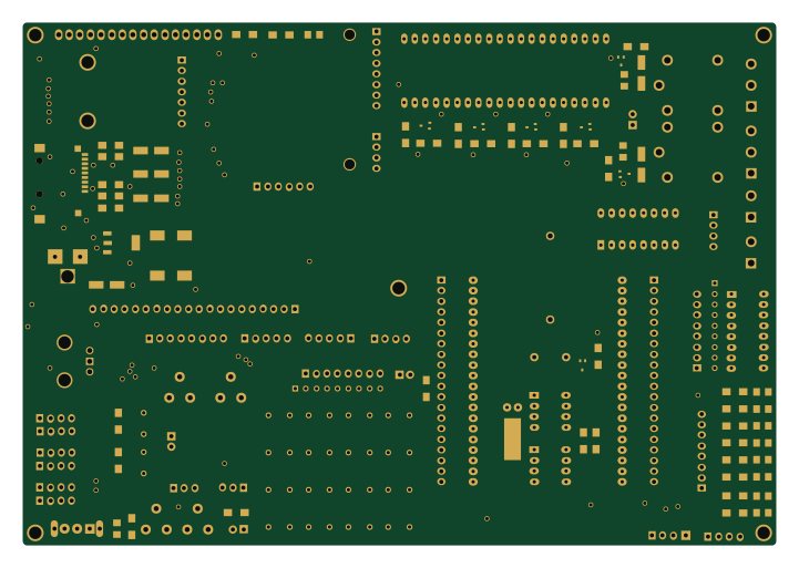
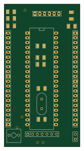
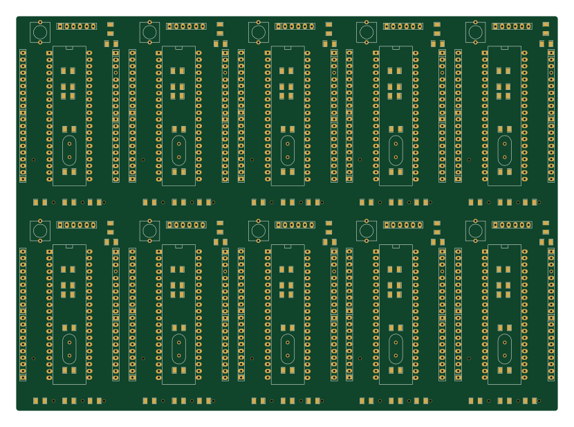
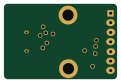
More boards in Pic16f877a_ExploreUltraPicDevKit
Similar boards
FW-EC-DongleHiderPlus
LeoDJ
28.2 × 26.1 mm14 parts4LCERN-OHL-W-2.0490
Flipper blackhat
o7-machinehum
91 × 53.1 mm167 parts4LCC-BY-NC-4.0292
Relatively-Universal-ROM-Programmer
AndersBNielsen
68.8 × 53.6 mm141 parts2LGPL-3.0253
Ovc5
osrf
98 × 97 mm197 parts6LApache-2.0208
Easy pdk programmer hardware
free-pdk
26.7 × 21.6 mm28 parts2LCC-BY-SA-4.0206
65uino
74.4 × 53.6 mm80 parts2LCustom license165