
Transmitter

About the Transmitter PCB
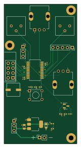
Transmitter is an open source PIC PCB design by finnhittson, published on GitHub. It is a 4-layer board measuring 38 × 72.6 mm, with 27 components from 20 distinct parts.
Its main chip is the PIC32MX170F256B, from the PIC family. Other key parts include the NRF24L01_Breakout and AMS1117-3.3. By type, the board carries 7 capacitors, 5 resistors, 3 ICs, 2 connectors, 2 switches and 2 diodes.
It belongs with the robotics & motion and power & battery designs in this gallery.
From the project
Because this project is intended to be a workshop only one version of code or main.c file is written for simplicity. Therefore, for the main.c to differentiate between running transmitter code and receiver, a GPIO pin on the micro is dedicated for this indication. The pin under q
Because this project is intended to be a workshop only one version of code or main.c file is written for simplicity. Therefore, for the main.c to differentiate between running transmitter code and receiver, a GPIO pin on the micro is dedicated for this indication. The pin under questions is RA5 (pin 2) from the tables below which descripe the pinout for the PIC16 in both the receiver and transmitter. If RA5 is pulled high, then the main.c executes transmitter code only. Similarly if RA5 is pulled low, then the main.c only executes receiver code.
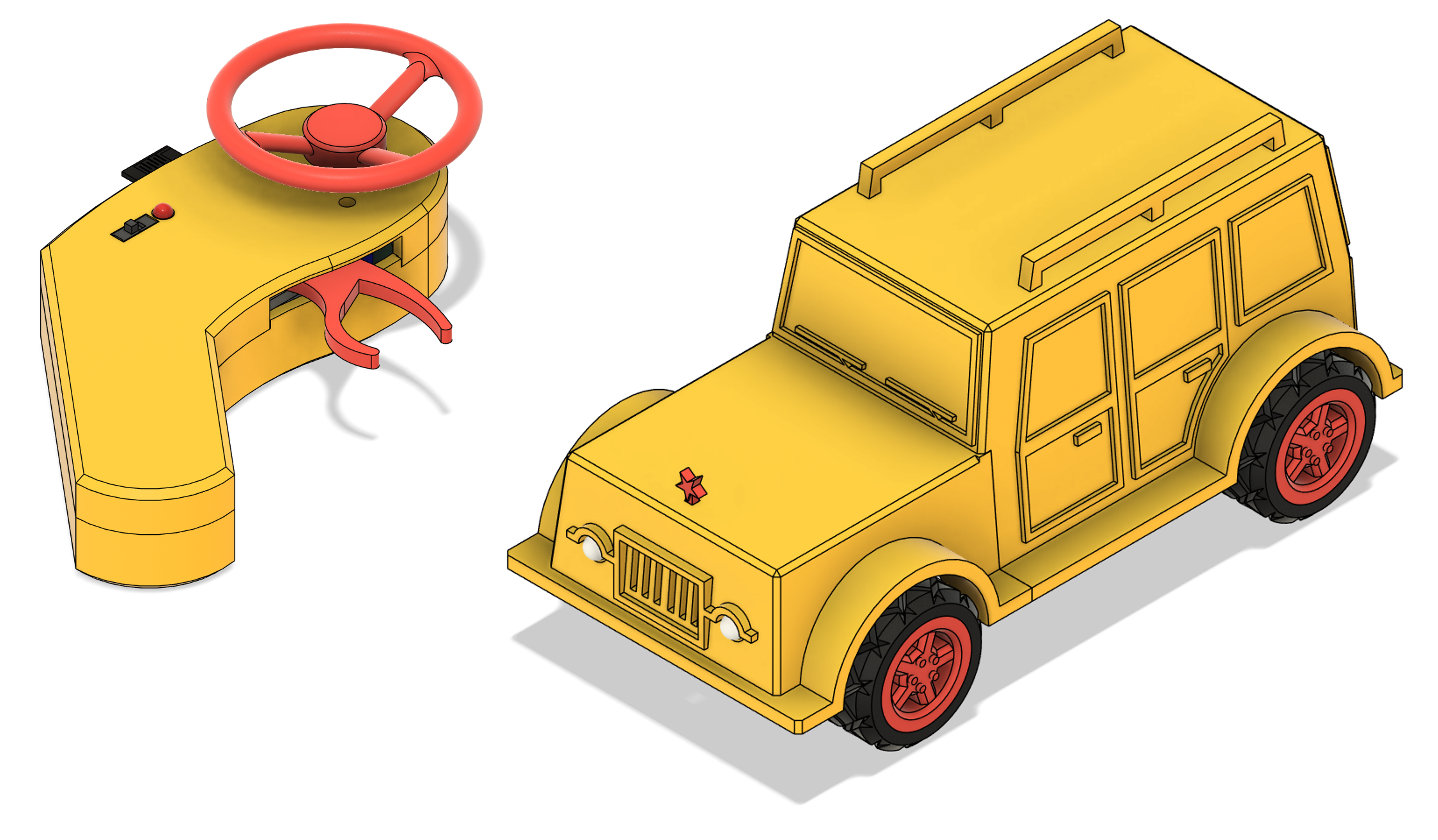
Main components on the Transmitter
Transmitter bill of materials (BOM)
27 components, 20 distinct parts — part numbers from the project's BOM.
| Qty | Part | Footprint | Refs |
|---|---|---|---|
| 1 | NRF24L01_Breakout | nRF24L01_Breakout | U2 |
| 1 | AMS1117-3.3 | SOT-223-3_TabPin2 | U3 |
| 1 | PIC32MX170F256B | SSOP28_MC_MCH | U4 |
| 1 | 2N7000 | SOT-23 | Q2 |
| 1 | Program | PinSocket_1x05_P2.54mm_Vertical | J1 |
| 1 | Debug | PinSocket_1x03_P2.54mm_Vertical | J2 |
| 1 | Battery_Cell | PinSocket_1x02_P2.54mm_Vertical | BT1 |
| 2 | Control Pot | TRIM_PT01-D115D-B502 | RV1, RV2 |
| 2 | Trim Pot | Potentiometer_Bourns_3386P_Vertical | RV3, RV4 |
| 1 | Power | PinSocket_1x03_P2.54mm_Vertical | SW1 |
| 1 | ~{MCLR} | SW_1825910-6-4 | SW2 |
| 2 | LED | LED_0402_1005Metric | D1, D2 |
| 1 | 10u | C_0805_2012Metric | C1 |
| 3 | 0.1u | C_0402_1005Metric | C2, C6, C8 |
| 1 | 220u | U2-K_NCH | C3 |
| 1 | 22u | CP_EIA-2012-15_AVX-P | C5 |
| 1 | 10u | C_0402_1005Metric | C7 |
| 2 | 470 | R_0402_1005Metric | R1, R6 |
| 2 | 10k | R_0402_1005Metric | R3, R5 |
| 1 | 1k | R_0402_1005Metric | R4 |
Transmitter design files
The KiCad project lives in the finnhittson/RC-Car-Build-Workshop repository on GitHub; these links point at the commit this page was built from.
Transmitter: common questions
What microcontroller does the Transmitter use?
The Transmitter is built around the PIC32MX170F256B, from the PIC family.
How big is the Transmitter PCB?
The Transmitter measures 38 × 72.6 mm, has 4 copper layers and is 1.6 mm thick.
How many components are on the Transmitter?
27 components, from 20 distinct parts, with part numbers taken from the project's own BOM. The full bill of materials is listed on this page.
Where can I download the Transmitter design files?
From the finnhittson/RC-Car-Build-Workshop repository on GitHub, which has the KiCad layout, the schematic and the BOM; the links under Design files point to each one.
Can I use the Transmitter design in my own project?
The repository has no license, so all rights stay with finnhittson. Use it as a reference, and ask the author before reusing the design.
Can I test firmware for the Transmitter without the hardware?
Yes. HardLabs builds a simulation of the board from its netlist and BOM, so you can run and debug PIC firmware against it before you order a PCB.
More boards in RC-Car-Build-Workshop
Similar boards
 PIC
PICPslab hardware
fossasia
99 × 53.3 mm187 parts4LApache-2.01.7k PIC
PICGB-LIVE32
Gekkio
51.4 × 61 mm46 parts4LCC-BY-4.0376 PIC
PICGB-MBCTEST
51.4 × 61 mm32 parts2LCC-BY-4.0376 PIC
PICGB-CARTPP-DIY
100 × 100 mm22 parts2LCC-BY-4.0376 PIC
PICGB-BENCH-G1
100 × 100 mm98 parts4LCC-BY-4.0376 PIC
PICGB-CARTPP-XC
80 × 55 mm19 parts2LCC-BY-4.0376