
Control module

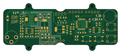
About the Control module
Control module is an open source STM32 PCB design by gabebuckmaster, published on GitHub under the MIT license. It is a 2-layer board measuring 96 × 40 mm, with 68 components from 38 distinct parts.
Its main chip is the STM32F042C6T6, from the STM32 family. Other key parts include the UC3843BD1G, AZ1117EH-3.3 and DS3231MZ. By type, the board carries 21 resistors, 19 capacitors, 9 connectors, 5 transistors, 4 ICs and 4 switches.
It belongs with the displays & leds, robotics & motion and power & battery designs in this gallery.
From the project
A minimalist nixie tube clock design in a cnc-machined hardwood case using IN12B tubes.
This PCB includes the microcontroller, a temperature compensated real time clock IC with battery backup, and the boost converter that generates the 180V supply for the nixie tubes.
For assembly, see the BOM and fab drawing
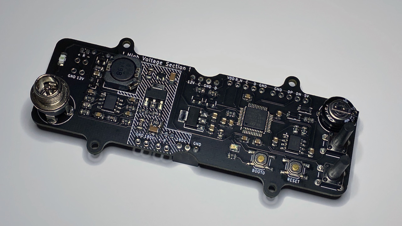
Main components on the Control module
Control module bill of materials (BOM)
68 components, 38 distinct parts — part numbers from the project's BOM.
| Qty | Part | Footprint | Refs |
|---|---|---|---|
| 1 | STM32F042C6T6 STM32F042C6Tx STMicroelectronics | LQFP-48_7x7mm_P0.5mm | U1 |
| 1 | UC3843BD1G UC3843_SOIC8 ON Semiconductor | SOIC-8_3.9x4.9mm_P1.27mm | U2 |
| 1 | AZ1117EH-3.3 Diodes Inc | SOT-223-3_TabPin2 | U3 |
| 1 | DS3231MZ Maxim Integrated | SOIC-8_3.9x4.9mm_P1.27mm | U4 |
| 3 | 2N7002 Generic | SOT-23 | Q1, Q2, Q3 |
| 1 | BSS84 Generic | SOT-23 | Q4 |
| 1 | IRFL214TRPBF IRFL214 Vishay Siliconix | SOT-223 | Q5 |
| 2 | Conn_01x05 | PinHeader_1x05_P2.54mm_Vertical_NoSilk | J1, J2 |
| 1 | CONN_01X03 | PinHeader_1x03_P2.54mm_Vertical | J3 |
| 1 | CONN_01X04 | PinHeader_1x04_P2.54mm_Vertical | J4 |
| 1 | PJ-064A CUI | PJ-064X | J5 |
| 4 | NOSTUFF | PinHeader_1x02_P2.54mm_Vertical | J101, J102, J103, J104 |
| 1 | 250 mA Generic | Fuse_1206_3216Metric_Pad1.42x1.75mm_HandSolder | F1 |
| 2 | SW_Push | SW_PUSH_6mm_H4.3mm | SW1, SW2 |
| 2 | SW_Push | SW_SPST_TL3342 | SW3, SW4 |
| 1 | BAT240AE6327HTSA1 BAT240 Infineon | SOT-23 | D1 |
| 2 | BAT54T1G BAT54 ON Semiconductor | D_SOD-123 | D2, D3 |
| 1 | GREEN_LED | LED_0805_2012Metric | D4 |
| 1 | CDRH105RNP-470NC 47u Sumida | L_TDK_SLF10145 | L1 |
| 5 | 100N 100n Generic | C_0805_2012Metric | C1, C2, C3, C4, C5 |
Show 18 more
| Qty | Part | Footprint | Refs |
|---|---|---|---|
| 4 | 1u Generic | C_0805_2012Metric | C6, C7, C8, C9 |
| 4 | 10U 10u Generic | C_0805_2012Metric | C10, C11, C12, C13 |
| 2 | 100n 250V Generic | C_1206_3216Metric | C14, C15 |
| 1 | 22N 22n Generic | C_0805_2012Metric | C16 |
| 1 | 240P 240p Generic | C_0805_2012Metric | C17 |
| 1 | 2.2NF 2.2nF Generic | C_0805_2012Metric | C18 |
| 1 | DX-5R5H334U Elna | EEC-S0HD334H | C19 |
| 8 | 4.99K 4.99k Generic | R_0805_2012Metric | R1, R2, R3, R4, R5, R6, R7, R8 |
| 1 | 4.99k 1% Generic | R_0805_2012Metric | R9 |
| 1 | 1 1% Generic | R_0805_2012Metric | R10 |
| 2 | 10 Generic | R_0805_2012Metric | R11, R12 |
| 2 | 100 Generic | R_0805_2012Metric | R13, R14 |
| 1 | 3.92k 1% Generic | R_0805_2012Metric | R16 |
| 1 | 22.1k 1% Generic | R_0805_2012Metric | R17 |
| 1 | 15k 1% Generic | R_1206_3216Metric | R18 |
| 1 | 340k 1% Generic | R_1206_3216Metric | R19 |
| 1 | 120 1/4W Generic | R_1206_3216Metric | R20 |
| 2 | NOSTUFF | R_0805_2012Metric | R101, R102 |
Control module design files
The KiCad project lives in the gabebuckmaster/nixie_clock repository on GitHub; these links point at the commit this page was built from.
Control module: common questions
What microcontroller does the Control module use?
The Control module is built around the STM32F042C6T6, from the STM32 family.
How big is the Control module?
The Control module measures 96 × 40 mm, has 2 copper layers and is 1 mm thick.
How many components are on the Control module?
68 components, from 38 distinct parts, with part numbers taken from the project's own BOM. The full bill of materials is listed on this page.
Where can I download the Control module design files?
From the gabebuckmaster/nixie_clock repository on GitHub, which has the KiCad layout and the BOM; the links under Design files point to each one.
Can I use the Control module design in my own project?
Yes, under the terms of its MIT license, which gabebuckmaster chose for the repository.
Can I test firmware for the Control module without the hardware?
Yes. HardLabs builds a simulation of the board from its netlist and BOM, so you can run and debug STM32 firmware against it before you order a PCB.
More boards in nixie_clock
Similar boards
 STM32
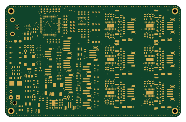
LumenPnP Motherboard
opulo-inc
149 × 95 mm296 parts4LCC-BY-SA-4.03.7k STM32
Base
google
52.3 × 52.3 mm36 parts2LApache-2.02.9k STM32
Main panel
234 × 84 mm26 parts4LApache-2.02.9k STM32
Type g
169 × 30 mm24 parts2LApache-2.02.9k STM32
Type a
150 × 30 mm14 parts2LApache-2.02.9k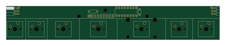 STM32
Type c
188 × 30 mm17 parts2LApache-2.02.9k