
Stimulator

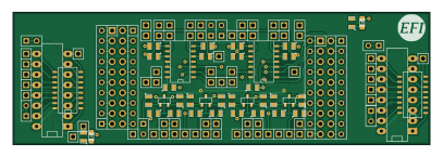
About the Stimulator PCB
Stimulator is an open source PCB design by glocklueng, published on GitHub. It is a 2-layer board measuring 101.6 × 32.4 mm, with 150 components from 16 distinct parts.
Other key parts include the MAX232 and MCP42010. By type, the board carries 82 connectors, 34 resistors, 22 capacitors, 6 ICs, 4 transistors and 2 diodes.
From the project
https://svn.code.sf.net/p/rusefi/code/trunk/
Main components on the Stimulator
Stimulator bill of materials (BOM)
150 components, 16 distinct parts — part numbers from the project's BOM.
| Qty | Part | Footprint | Refs |
|---|---|---|---|
| 2 | MAX232 | DIP-16__300_ELL | U1, U6 |
| 4 | MCP42010 | SO14N | U2, U3, U4, U5 |
| 4 | 2N7002 | sot23 | Q1, Q2, Q3, Q4 |
| 67 | CONN_1 | PIN_ARRAY_1 | P1, P2, P3, P4, P5, P6, P9, P10 +59 |
| 7 | TEST | SIL-2 | P7, P8, P23, P25, P40, P78, P79 |
| 4 | CONN_10 | SIL-10 | P15, P24, P64, P75 |
| 2 | CONN_10X2 | Pin_Header_Straight_2x10 | P19, P70 |
| 2 | DIL16 | SO16N | P80, P81 |
| 1 | ECU PWR | LED-0805 | D1 |
| 1 | STIM PWR | LED-0805 | D2 |
| 14 | 1uF | SM0805 | C1, C2, C3, C4, C5, C6, C7, C16 +6 |
| 4 | 100 pF | SM0805 | C8, C9, C14, C15 |
| 4 | 0.1uF | SM0805 | C10, C11, C12, C13 |
| 16 | 10k | SM0805 | R1, R2, R4, R5, R6, R7, R16, R17 +8 |
| 2 | 700R | SM0805 | R3, R32 |
| 16 | 0 | SM0805 | R8, R9, R10, R11, R12, R13, R14, R15 +8 |
Stimulator design files
The KiCad project lives in the glocklueng/rusefi repository on GitHub; these links point at the commit this page was built from.
Stimulator: common questions
How big is the Stimulator PCB?
The Stimulator measures 101.6 × 32.4 mm, has 2 copper layers and is 1.6 mm thick.
How many components are on the Stimulator?
150 components, from 16 distinct parts, with part numbers taken from the project's own BOM. The full bill of materials is listed on this page.
Where can I download the Stimulator design files?
From the glocklueng/rusefi repository on GitHub, which has the KiCad layout and the BOM; the links under Design files point to each one.
Can I use the Stimulator design in my own project?
The repository has no license, so all rights stay with glocklueng. Use it as a reference, and ask the author before reusing the design.
More boards in rusefi
 STM32
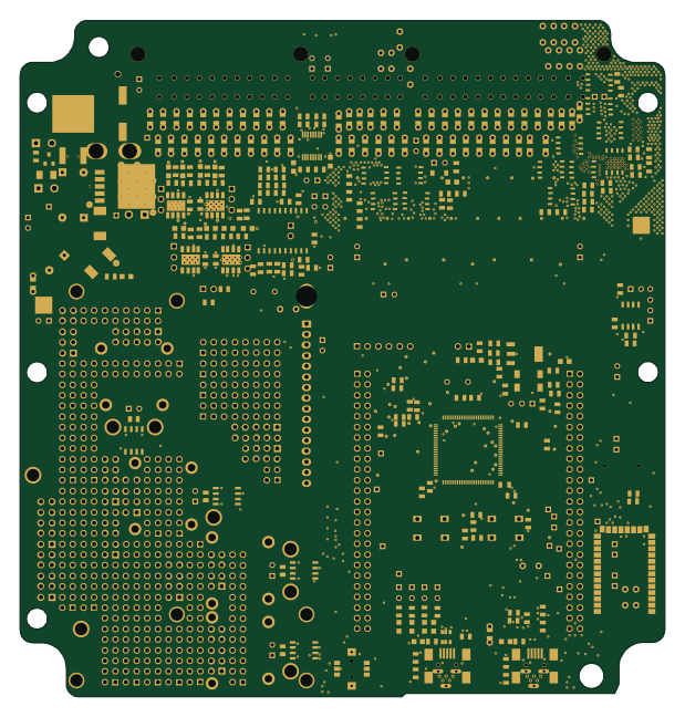
STM32Frankenso
154.1 × 161.7 mm565 parts2LNo license0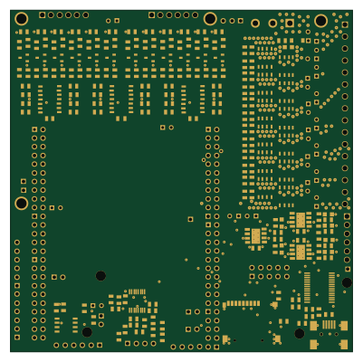
High or low side drive board for RUSEFI.com
100 × 100 mm256 parts2LNo license0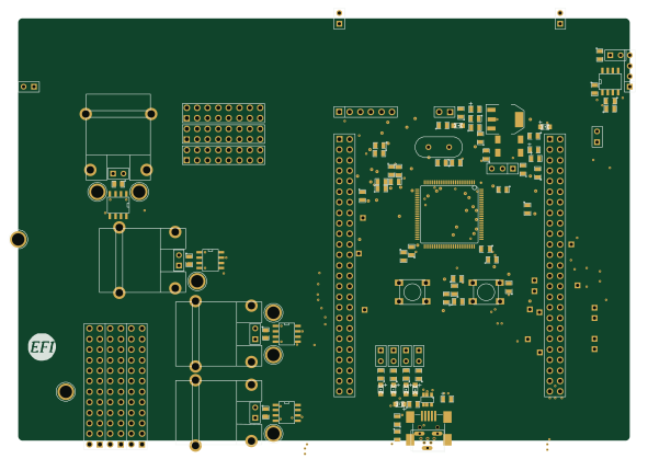 STM32
STM32TCPL-STM-CAN
147.6 × 102 mm127 parts2LNo license0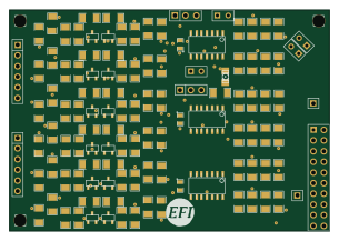
Adc amp divider
76.2 × 52.7 mm118 parts2LNo license0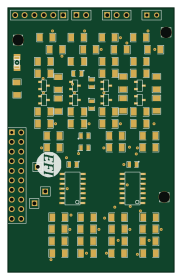
Adc amp divider vert
44 × 70 mm81 parts2LNo license0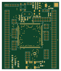 STM32
STM32176 pin board
61.8 × 73.2 mm76 parts2LNo license0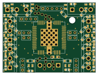
Breakout TLE6244
50.8 × 38.1 mm73 parts2LNo license0 STM32
STM32Stm32f407 board
61.8 × 73.2 mm66 parts2LNo license0
Inj 12ch
47 × 58.9 mm59 parts2LNo license0
VR board
27.3 × 17.8 mm28 parts2LNo license0
284617-1
150 × 50 mm25 parts2LNo license0