
108 open source boards using the MAX232
Real designs built with the MAX232, from public GitHub projects: a quick way to see how others power, decouple and connect it. Each board comes with its KiCad files, full parts list and a render — and you can simulate its firmware on HardLabs.
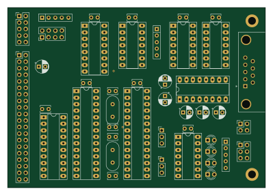 AVR/Arduino
TTY
KALTCHUK
99.7 × 69.9 mm43 parts2LNo license94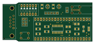
USB-2-232
LimeProgramming
79.7 × 35.1 mm22 parts2LMPL-2.049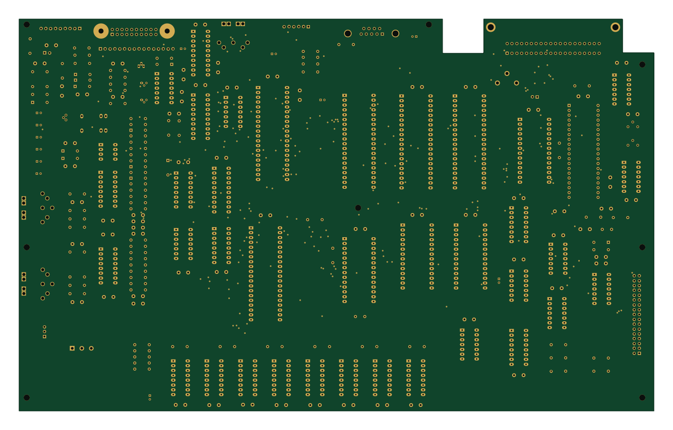
Dragon64
danwerner21
333.2 × 205.9 mm220 parts2LNo license34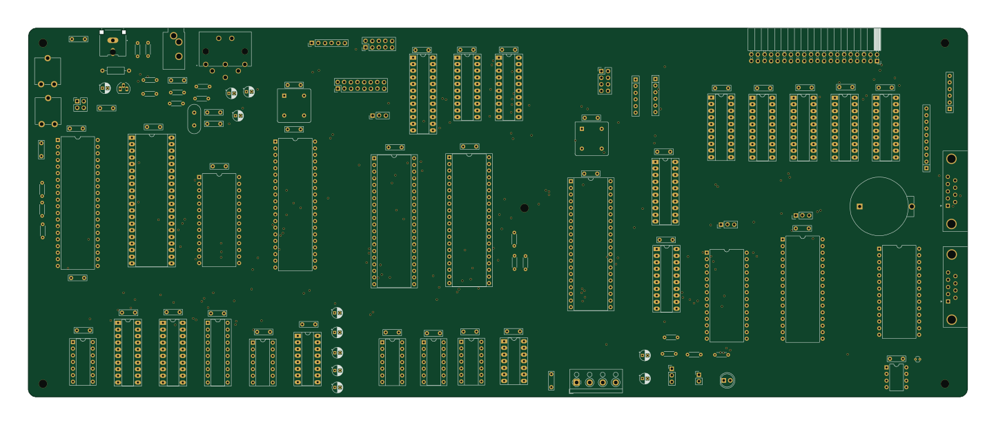
We816
360.1 × 141.4 mm128 parts2LNo license32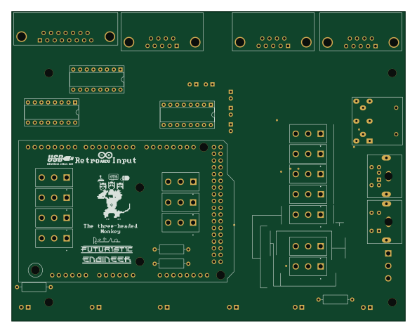 AVR/Arduino
RetroARDUInput
RetroFuturisticEngineer
148.3 × 116.6 mm37 parts2LLGPL-2.125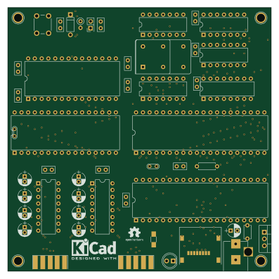
6809v2
jbevren
99.1 × 99.1 mm52 parts2LNo license22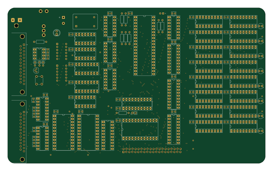
Fennec6800
ChartreuseK
218 × 131.9 mm113 parts2LBSD-3-Clause20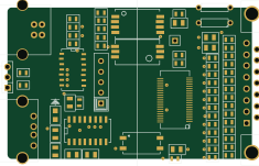 PIC
EvBMS
Greg-Fordyce
58.8 × 36.5 mm68 parts2LNo license18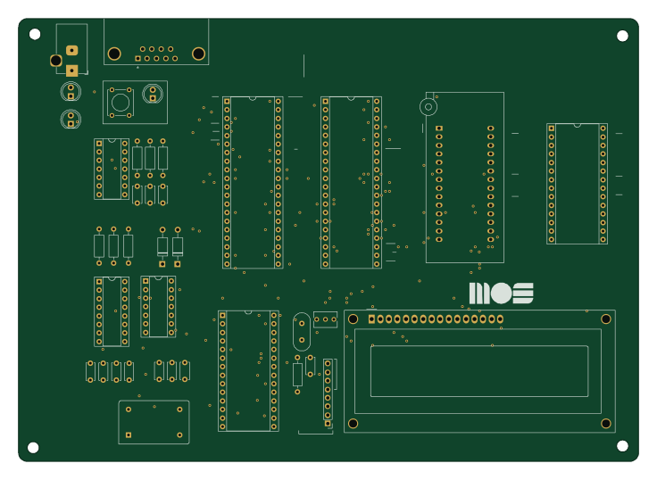
6502-wozmon
tsanders30004
183.7 × 131.3 mm38 parts2LNo license15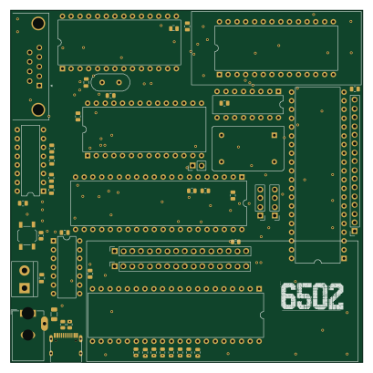
6502Rev2
stuenkels
102 × 102 mm60 parts4LNo license11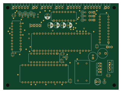 AVR/Arduino
Cat644
carangil
101.6 × 76.2 mm46 parts2LGPL-2.011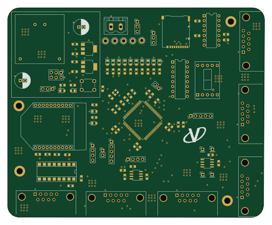 STM32
MVCU F407
Vaaarad07
132.9 × 108.4 mm100 parts4LMIT10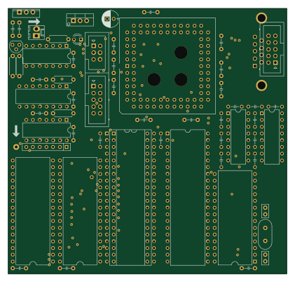
UMMF
nils-eilers
105 × 100 mm63 parts2LNo license10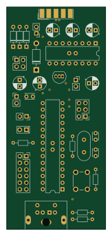 AVR/Arduino
Pontag
hkzlab
38.1 × 85.1 mm35 parts2LGPL-3.09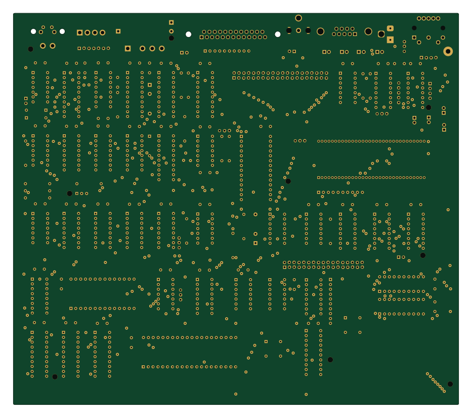
TIM-011B
Board-Folk
232.8 × 204.2 mm149 parts2LNo license8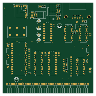
SER-enhanced
Creep69
100 × 100 mm41 parts2LNo license8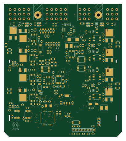 STM32
Parkbrake
mumme74
101.6 × 114.3 mm353 parts2LNo license7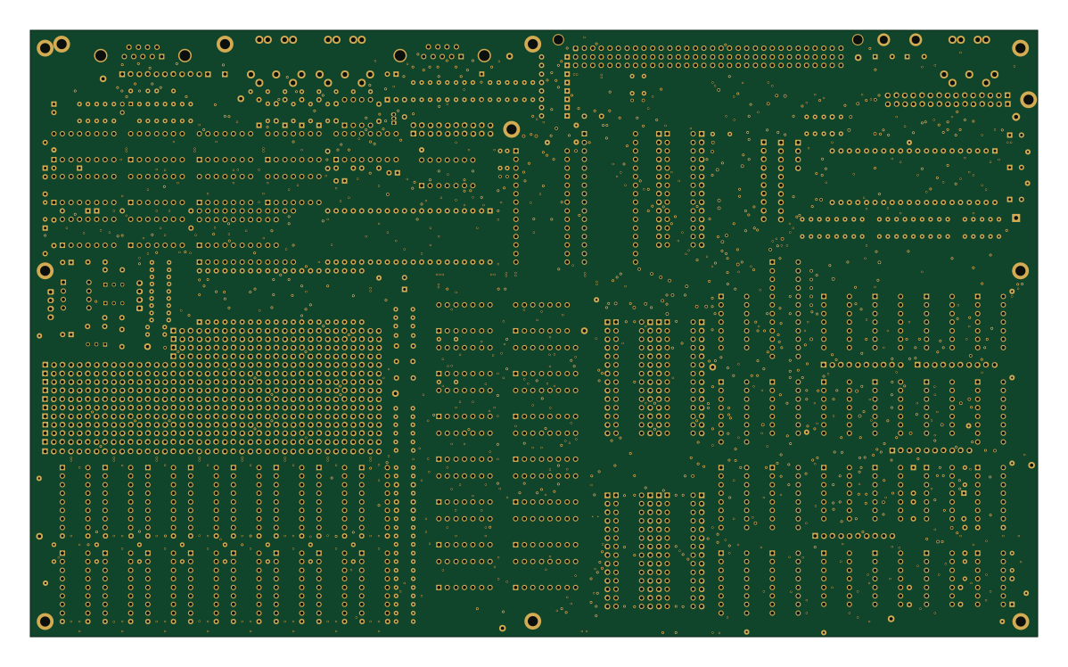
Main
ceteras
299.2 × 180 mm434 parts2LMIT5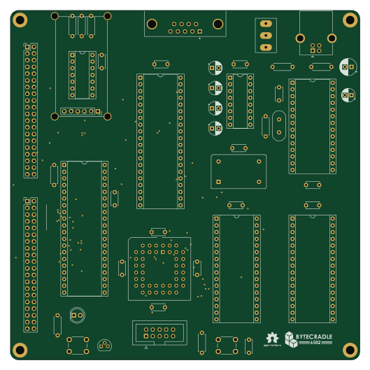
ByteCradle 6502 MINI BOARD
ifilot
132.1 × 132.1 mm49 parts4LGPL-3.05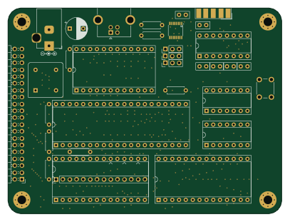
Minimal-6502
techav-homebrew
101.6 × 76.2 mm30 parts2LNo license5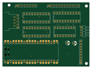 RP2040/RP2350
Pico-Scanned-Keyboard-Matrix-Emulator
stephen-usher
81 × 60 mm17 parts2LCC0-1.05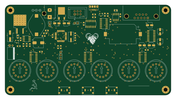 AVR/Arduino
Nixiedisp
jtsiomb
140 × 76.1 mm224 parts2LGPL-3.03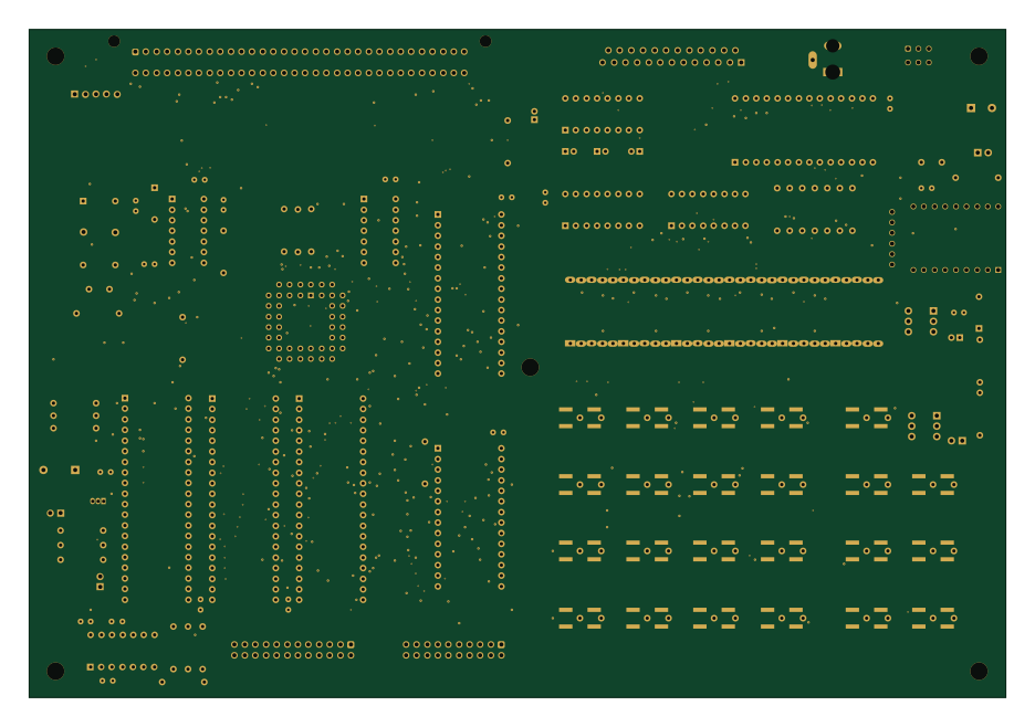
JC2 v4.1
Emile666
233.7 × 160 mm120 parts2LNo license3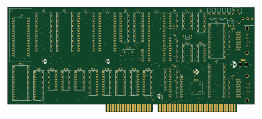
6309-Unleashed
FredericSegard
252.7 × 106.7 mm95 parts2LNo license3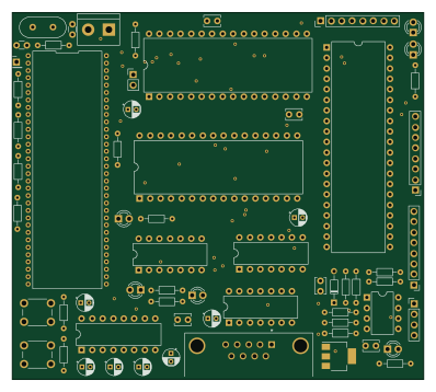
Z180-comp
89Mods
99.3 × 88.7 mm63 parts4LMIT3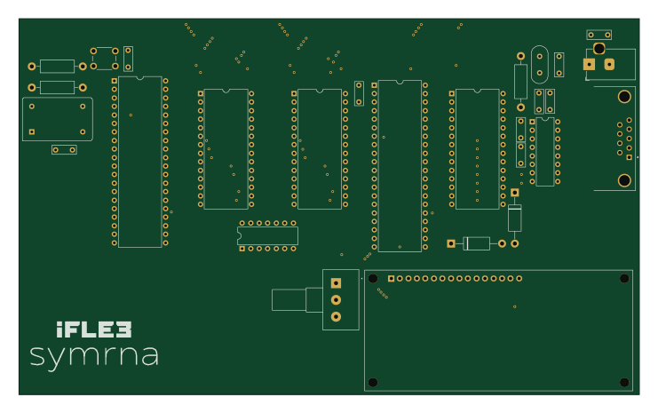
Ifle3-symrna
barkolorious
184.9 × 112 mm27 parts2LNo license3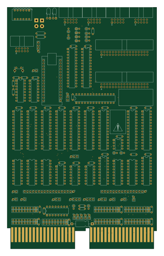 AVR/Arduino
Utracer11
j-hoppe
132.3 × 214.1 mm128 parts4LBSD-3-Clause2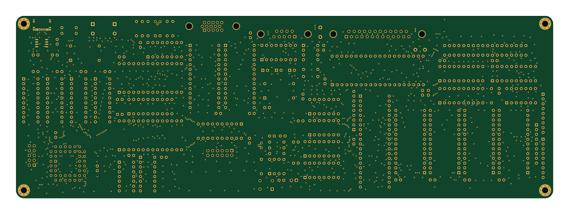
FellaPC
agkaminski
284.9 × 96.5 mm107 parts2LCC0-1.02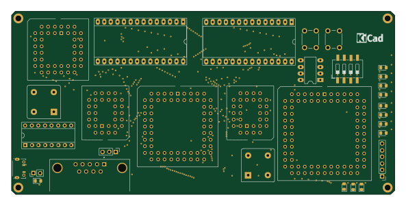
Mcd
jack-mil
148 × 70.8 mm69 parts2LNo license2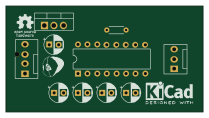
MinitelInterface
assoRED
52.1 × 27.9 mm10 parts2LMIT2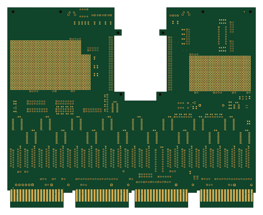
Unibone.unrouted
QUniBone
265.6 × 214.1 mm1309 parts4LBSD-2-Clause1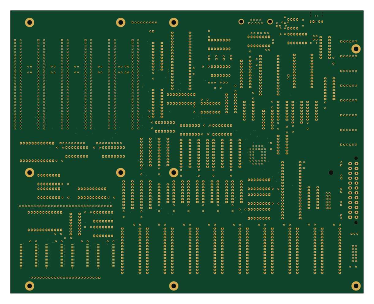
Hydra-16
danstruthers
304.8 × 243.8 mm199 parts6LNo license1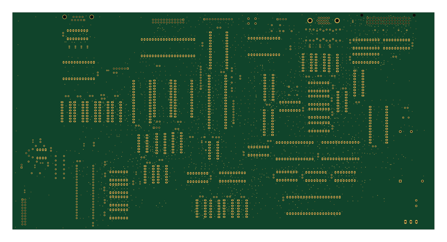
OSM39
christophetoularastel-eng
388.1 × 200 mm186 parts2LGPL-3.01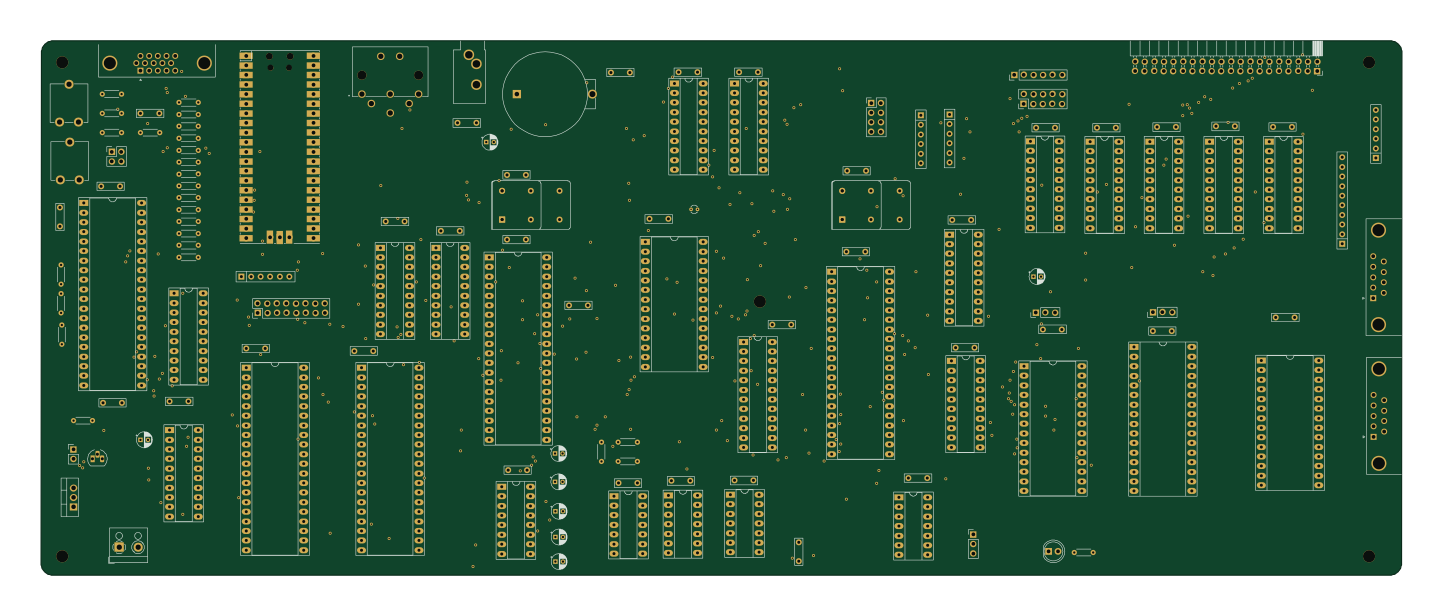 RP2040/RP2350
We816-mark2
360.1 × 141.4 mm128 parts2LNo license1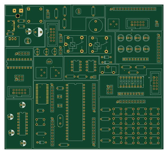 PIC
PIC DEV BOARD
anshukumar146
140.7 × 128.5 mm102 parts4LNo license1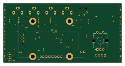
Dew-Controller
kuellenberg
100 × 50 mm92 parts2LNo license1
How designs wire the MAX232
Read from the KiCad layouts of 90 open source designs, one per repository: what each pin of the MAX232 connects to, and the resistors, capacitors and other passives placed on it.
- The C1+ pin has a series capacitor on 89 of 90 designs, most often 1 µF (then 10 µF).
- The C1- pin has a series capacitor on 89 of 90 designs, most often 1 µF (then 10 µF).
- The C2+ pin has a series capacitor on 89 of 90 designs, most often 1 µF (then 10 µF).
- The C2- pin has a series capacitor on 89 of 90 designs, most often 1 µF (then 10 µF).
| Pin | Connected to | Parts on the pin |
|---|---|---|
| C1+pin 1 | Connected to: Signal 99% |
|
| VS+pin 2 | Connected to: Signal 97% |
|
| C1-pin 3 | Connected to: Signal 99% |
|
| C2+pin 4 | Connected to: Signal 99% |
|
| C2-pin 5 | Connected to: Signal 99% |
|
| VS-pin 6 | Connected to: Signal 98% |
|
| GNDpin 15 | Connected to: GND 98% | — |
| VCCpin 16 | Connected to: 5V 82% · a signal 18% |
|
8 more pins vary from design to design. Connections count pins, parts count designs; values in brackets are how many parts had that value. Designs read include Stimulator by rusefi, TTY by KALTCHUK, DuPal DIP by DuPAL-PAL-DUmper and USB-2-232 by LimeProgramming.
The MAX232 in open source designs
The gallery holds 108 open source boards using the MAX232 from 95 GitHub repositories; a typical one measures about 132.3 × 100 mm and carries around 62 components.
81% are two-layer designs, the rest use four layers or more, and 41% carry an open source license.
The most starred is Stimulator by rusefi.
Parts used alongside the MAX232
Microcontrollers on boards using the MAX232
What boards using the MAX232 are built for
MAX232: common questions
Where can I find a MAX232 reference design?
Each of the 108 boards on this page is a real design using the MAX232. Open one to see how it is wired up, with the full BOM, a render of the layout and links to its KiCad files.
How is the MAX232 C1+ pin connected?
The C1+ pin has a series capacitor on 89 of 90 designs, most often 1 µF (then 10 µF). Counted from the KiCad layouts of 90 open source designs using the MAX232.
How is the MAX232 C1- pin connected?
The C1- pin has a series capacitor on 89 of 90 designs, most often 1 µF (then 10 µF). Counted from the KiCad layouts of 90 open source designs using the MAX232.
How is the MAX232 C2+ pin connected?
The C2+ pin has a series capacitor on 89 of 90 designs, most often 1 µF (then 10 µF). Counted from the KiCad layouts of 90 open source designs using the MAX232.
What parts are used alongside the MAX232?
The 74LS04, 74HC245, 74LS00, 74LS245 and 74LS32 appear in the most repositories here.
Which microcontrollers do boards using the MAX232 use?
Most are built on AVR/Arduino (21), RP2040/RP2350 (4), PIC (4) and Raspberry Pi (2).
How big is a typical board using the MAX232?
The median is 132.3 × 100 mm, and 81% are two-layer designs.
What is the most popular open source board using the MAX232?
By GitHub stars, Stimulator by rusefi, with 1,177 stars.
Can I simulate one of these boards using the MAX232 before building it?
Yes. HardLabs turns a board's netlist and BOM into a working simulation, so you can boot and test firmware against it with no hardware on your desk.