
Esp32-hdmi quad splitter

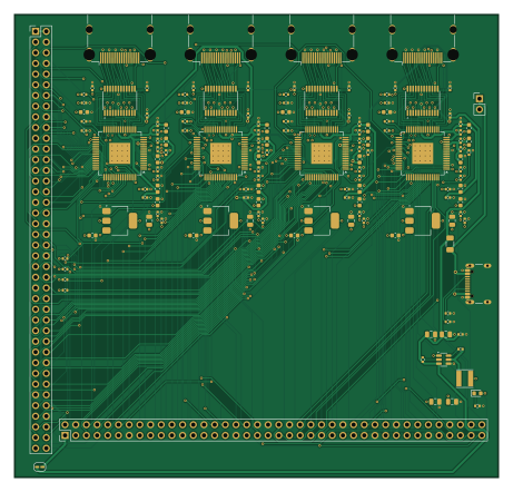
About the Esp32-hdmi quad splitter PCB
Esp32-hdmi quad splitter is an open source PCB design by gyuhooo, published on GitHub under the MIT license. It is a 4-layer board measuring 115 × 110 mm, with 142 components from 25 distinct parts.
Other key parts include the AP63203WU-7, ADV7513BSWZ, TPD12S016PWR and TLV1117LV18DCYR. By type, the board carries 86 capacitors, 24 resistors, 13 ICs, 9 inductors, 8 connectors and 1 fuse.
From the project
ESP32 + Lontium LT86104SX による HDMI 1入力→4出力 (Full HD) スプリッタの検討・設計情報
FPGA ボードから 24bit RGB ×4 を受け、HDMI 4 本を出す基板の KiCad 7 プロジェクト。 gen/genschematic.py が回路図・BOM・ピン割り当て表を生成し、kicad-cli` でネットリストと PDF を書き出している。
- USB-C(GCT USB4105-GF-A、USB2.0 16P)、CC1/CC2 に 5.1 kΩ(5 V 3 A シンク宣言)。代替 5 V 入力 J6。 - F1: PTC 2 A。+5V と VBUS に PWRFLAG。 - U5 AP63203WU(3.3 V 固定、2 A): CIN 10 µF ×2、CBST 0.1 µF、L 4.7 µH(NR4018T4R7M)、COUT 22 µF ×2、EN は 100 kΩ で VIN へ。 - 消費見積: 1.8 V 系 4 × 142 mA ≈ 0.57 A(LDO 損失 ≈ 0.85 W、SOT-223 ×4 に分散)、3.3 V 系合計 ≈ 0.7 A、5 V 入力 ≈ 0.8 A(HDMI 5VOUT 4 × 55 mA 含む)。 - JP1(ソルダージャンパ)を閉じると J7/J8 の 1-2 ピンから FPGA ボードへ 5 V を供給できる。FPGA ボードが自前電源のときは開けたままにする。
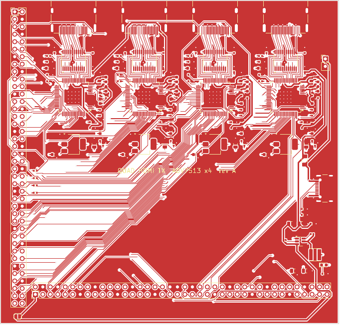
Main components on the Esp32-hdmi quad splitter
Esp32-hdmi quad splitter bill of materials (BOM)
142 components, 25 distinct parts — part numbers from the project's BOM.
| Qty | Part | Footprint | Refs |
|---|---|---|---|
| 1 | AP63203WU-7 AP63203WU | TSOT-23-6 | U5 |
| 4 | ADV7513BSWZ | LQFP-64-1EP_10x10mm_P0.5mm_EP5x5mm_ThermalVias | U11, U21, U31, U41 |
| 4 | TPD12S016PWR | TSSOP-24_4.4x7.8mm_P0.65mm | U12, U22, U32, U42 |
| 4 | TLV1117LV18DCYR | SOT-223-3_TabPin2 | U13, U23, U33, U43 |
| 4 | 208658-1001 HDMI_A | HDMI_A_Molex_208658-1001_Horizontal | J1, J2, J3, J4 |
| 1 | USB4105-GF-A USB-C 5V in | USB_C_Receptacle_GCT_USB4105-xx-A_16P_TopMnt_Horizontal | J5 |
| 1 | 5V ALT IN | PinHeader_1x02_P2.54mm_Vertical | J6 |
| 1 | PH2-80-UA FPGA_J7 | PinHeader_2x40_P2.54mm_Vertical | J7 |
| 1 | PH2-80-UA FPGA_J8 | PinHeader_2x40_P2.54mm_Vertical | J8 |
| 1 | 1206L200/12SLYR 2A | Fuse_1206_3216Metric | F1 |
| 1 | LTST-C193KGKT-5A PWR | LED_0603_1608Metric | D1 |
| 8 | BLM18PG121SN1D 120R@100MHz | L_0603_1608Metric | FB11, FB12, FB21, FB22, FB31, FB32, FB41, FB42 |
| 1 | NR4018T4R7M 4.7uH | L_Taiyo-Yuden_NR-40xx | L1 |
| 58 | GRM155R71C104KA88D 0.1uF | C_0402_1005Metric | C51, C54, C103, C104, C105, C106, C107, C109 +50 |
| 2 | GRM21BR61A106KE19L 10uF | C_0805_2012Metric | C52, C53 |
| 6 | GRM21BR60J226ME39L 22uF | C_0805_2012Metric | C55, C56, C102, C202, C302, C402 |
| 12 | GRM188R60J106ME47D 10uF | C_0603_1608Metric | C101, C108, C112, C201, C208, C212, C301, C308 +4 |
| 8 | GRM188R61A105KA61D 1uF | C_0603_1608Metric | C115, C118, C215, C218, C315, C318, C415, C418 |
| 4 | RC0402FR-074K7L 4.7k | R_0402_1005Metric | R1, R2, R3, R4 |
| 2 | RC0402FR-075K1L 5.1k | R_0402_1005Metric | R5, R6 |
Show 5 more
| Qty | Part | Footprint | Refs |
|---|---|---|---|
| 1 | RC0402FR-07100KL 100k | R_0402_1005Metric | R7 |
| 1 | RC0402FR-071KL 1k | R_0402_1005Metric | R8 |
| 4 | RC0402FR-07887RL 887R 1% | R_0402_1005Metric | R11, R21, R31, R41 |
| 8 | RC0402FR-0710KL 10k | R_0402_1005Metric | R12, R13, R22, R23, R32, R33, R42, R43 |
| 4 | RC0402FR-070RL 0R | R_0402_1005Metric | R14, R24, R34, R44 |
Esp32-hdmi quad splitter design files
The KiCad project lives in the gyuhooo/esp32-hdmi-quad-splitter repository on GitHub; these links point at the commit this page was built from.
Esp32-hdmi quad splitter: common questions
How big is the Esp32-hdmi quad splitter PCB?
The Esp32-hdmi quad splitter measures 115 × 110 mm, has 4 copper layers and is 1.6 mm thick.
How many components are on the Esp32-hdmi quad splitter?
142 components, from 25 distinct parts, with part numbers taken from the project's own BOM. The full bill of materials is listed on this page.
Where can I download the Esp32-hdmi quad splitter design files?
From the gyuhooo/esp32-hdmi-quad-splitter repository on GitHub, which has the KiCad layout, the schematic and the BOM; the links under Design files point to each one.
Can I use the Esp32-hdmi quad splitter design in my own project?
Yes, under the terms of its MIT license, which gyuhooo chose for the repository.