
Impedance testboard

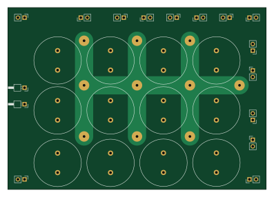
About the Impedance testboard PCB
Impedance testboard is an open source PCB design by hb020, published on GitHub. It is a 2-layer board measuring 99.1 × 69.9 mm, with 38 components from 19 distinct parts.
By type, the board carries 16 connectors, 15 capacitors and 7 resistors.
It belongs with the power & battery and test & measurement designs in this gallery.
From the project
Handheld Battery AC and Time Domain characterization tool on Attiny series 2
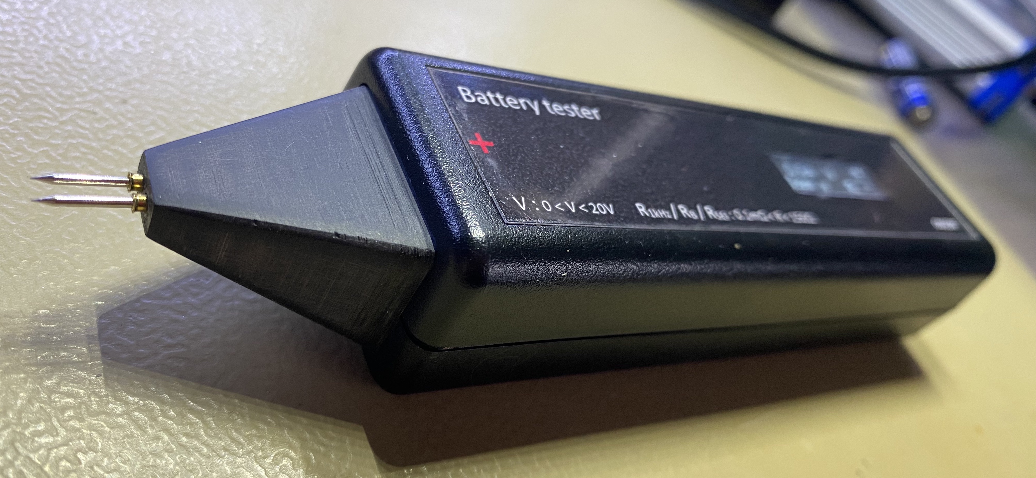
This repository is about a "pen size" (handheld) tool for quick measurement of various types of battery resistances/impedances.
This tool uses 2 different methods for measuring impedance values:
- "standard" AC 1 kHz impedance, as used by many. - Direct Current Impedance Spectroscopy, extracting the bulk (solution) resistance and the SEI (Solid Electrolyte Interphase) resistance, allowing better insight in both battery ageing and battery safety. Normally this would require a lengthy procedure via EIS (Electrochemical Impedance Spectroscopy) and model fitting. This tool allows to do it fast…
Impedance testboard bill of materials (BOM)
38 components, 19 distinct parts — part numbers from the project's BOM.
| Qty | Part | Footprint | Refs |
|---|---|---|---|
| 14 | Conn_01x02_Male | PinHeader_1x02_P2.54mm_Vertical | J1, J2, J5, J6, J7, J8, J9, J10 +6 |
| 2 | Conn_01x01_Female | PinHeader_1x01_P2.54mm_Horizontal | J3, J4 |
| 1 | T491A106M020AT 10uF | C_1206_3216Metric_Pad1.33x1.80mm_HandSolder | C1 |
| 1 | CL10B105KO8NNNC 1uF | C_1206_3216Metric_Pad1.33x1.80mm_HandSolder | C2 |
| 1 | CL10B104KO8NNNC 100nF | C_1206_3216Metric_Pad1.33x1.80mm_HandSolder | C3 |
| 3 | CL10A475KO8NNNC 10000uF | C_Radial_D18.0mm_H35.5mm_P7.50mm | C4, C5, C15 |
| 2 | T491A106M020AT 10000uF | C_Radial_D18.0mm_H35.5mm_P7.50mm | C6, C9 |
| 3 | CL10B105KO8NNNC 10000uF | C_Radial_D18.0mm_H35.5mm_P7.50mm | C7, C13, C14 |
| 1 | CC0603JRNPO9BN680 10000uF | C_Radial_D18.0mm_H35.5mm_P7.50mm | C8 |
| 1 | CC0603JRNPO9BN330 10000uF | C_Radial_D18.0mm_H35.5mm_P7.50mm | C10 |
| 1 | CL10A226MP8NUNE 10000uF | C_Radial_D18.0mm_H35.5mm_P7.50mm | C11 |
| 1 | CL10A106KP8NNND 10000uF | C_Radial_D18.0mm_H35.5mm_P7.50mm | C12 |
| 1 | RC0603FR-0710KL 1R | R_1206_3216Metric_Pad1.30x1.75mm_HandSolder | R1 |
| 1 | RC0603FR-0722KL 1R | R_1206_3216Metric_Pad1.30x1.75mm_HandSolder | R2 |
| 1 | RC0603FR-0722KL 0.1R | R_1206_3216Metric_Pad1.30x1.75mm_HandSolder | R3 |
| 1 | RC0603FR-071ML 0.1R | R_1206_3216Metric_Pad1.30x1.75mm_HandSolder | R4 |
| 1 | RC0603FR-07316KL 0.1R | R_1206_3216Metric_Pad1.30x1.75mm_HandSolder | R5 |
| 1 | RC0603FR-07499KL 0.1R | R_1206_3216Metric_Pad1.30x1.75mm_HandSolder | R6 |
| 1 | RC0603FR-07287KL 0.1R | R_1206_3216Metric_Pad1.30x1.75mm_HandSolder | R7 |
Impedance testboard design files
The KiCad project lives in the hb020/batterymeter repository on GitHub; these links point at the commit this page was built from.
Impedance testboard: common questions
How big is the Impedance testboard PCB?
The Impedance testboard measures 99.1 × 69.9 mm, has 2 copper layers and is 1.6 mm thick.
How many components are on the Impedance testboard?
38 components, from 19 distinct parts, with part numbers taken from the project's own BOM. The full bill of materials is listed on this page.
Where can I download the Impedance testboard design files?
From the hb020/batterymeter repository on GitHub, which has the KiCad layout, the schematic and the BOM; the links under Design files point to each one.
Can I use the Impedance testboard design in my own project?
The repository has no license, so all rights stay with hb020. Use it as a reference, and ask the author before reusing the design.
More boards in batterymeter
Similar boards
StackLink
gusmanb
52.3 × 10.5 mm5 parts2LGPL-3.05.0k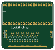
AnalyzerBoxPCB fork
52.7 × 47.9 mm54 parts4LGPL-3.05.0k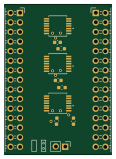
LevelShifter
28.3 × 39.8 mm21 parts2LGPL-3.05.0k
EinkPDA screen
TalismanDesign
95 × 54 mm27 parts2LApache-2.02.0k
Stack chan
stack-chan
50 × 50 mm33 parts2LApache-2.01.7k
Display Carrier
AxxAxx
35.6 × 58.2 mm5 parts2LGPL-3.01.7k