
RF Detector

About the RF Detector PCB
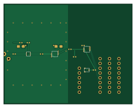
RF Detector is an open source AVR/Arduino PCB design by himanshu40304, published on GitHub. It is a 4-layer board measuring 68 × 53 mm, with 21 components from 15 distinct parts.
Its main chip is the ARDUINO_POWER, from the AVR/Arduino family. Other key parts include the PGA-103+, AD8313, ADS7042 and REF3312. By type, the board carries 9 capacitors, 5 connectors, 4 ICs, 2 resistors and 1 inductor.
From the project
This repository contains the automation workflow and some projects made by using this workflow which makes pcb designs using ai assistance faster than making pcb designs manually.
An autonomous, end-to-end PCB design, verification, and manufacturing pipeline powered by KiCad 10, SPICE, OpenEMS 3D FDTD, ParaView, and AI-driven Automation Agents.
⭐ If you find this repository useful for your PCB workflows or research, please consider giving it a star!
This repository contains automated workflows, design tools, and complete hardware projects demonstrating AI-assisted schematic creation, SPICE verification, electrical rules check (ERC), automated component placement, routing, clearance isolation, and design rules check (DRC).
Main components on the RF Detector
RF Detector bill of materials (BOM)
21 components, 15 distinct parts — part numbers from the project's BOM.
| Qty | Part | Footprint | Refs |
|---|---|---|---|
| 1 | PGA-103+ | SOT-363_SC-70-6 | U1 |
| 1 | AD8313 | MSOP-8_3x3mm_P0.65mm | U2 |
| 1 | ADS7042 | SOT-23-8 | U3 |
| 1 | REF3312 | SOT-23 | U4 |
| 1 | SMA_EDGE | SMA_Amphenol_132289_EdgeMount | J1 |
| 1 | ARDUINO_POWER | PinHeader_1x08_P2.54mm_Vertical | J2 |
| 1 | ARDUINO_DIGITAL_0-7 | PinHeader_1x08_P2.54mm_Vertical | J3 |
| 1 | ARDUINO_ANALOG | PinHeader_1x06_P2.54mm_Vertical | J4 |
| 1 | ARDUINO_DIGITAL_8-13_SPI | PinHeader_1x08_P2.54mm_Vertical | J5 |
| 1 | 600R@100MHz | L_0402_1005Metric | FB1 |
| 2 | 100pF | C_0402_1005Metric | C1, C2 |
| 5 | 100nF | C_0402_1005Metric | C3, C4, C6, C8, C9 |
| 2 | 10uF | C_0805_2012Metric | C5, C7 |
| 1 | 33R | R_0402_1005Metric | R1 |
| 1 | 1k | R_0402_1005Metric | R2 |
RF Detector design files
The KiCad project lives in the himanshu40304/PCB_automation repository on GitHub; these links point at the commit this page was built from.
RF Detector: common questions
What microcontroller does the RF Detector use?
The RF Detector is built around the ARDUINO_POWER, from the AVR/Arduino family.
How big is the RF Detector PCB?
The RF Detector measures 68 × 53 mm, has 4 copper layers and is 1.6 mm thick.
How many components are on the RF Detector?
21 components, from 15 distinct parts, with part numbers taken from the project's own BOM. The full bill of materials is listed on this page.
Where can I download the RF Detector design files?
From the himanshu40304/PCB_automation repository on GitHub, which has the KiCad layout, the schematic and the BOM; the links under Design files point to each one.
Can I use the RF Detector design in my own project?
The repository has no license, so all rights stay with himanshu40304. Use it as a reference, and ask the author before reusing the design.
Can I test firmware for the RF Detector without the hardware?
Yes. HardLabs builds a simulation of the board from its netlist and BOM, so you can run and debug AVR/Arduino firmware against it before you order a PCB.
More boards in PCB_automation
Binary Counter 8Bit
70 × 45 mm31 parts2LNo license1 ESP32
ESP32Test backup
100 × 30 mm30 parts2LNo license1 ESP32
ESP32Converter v9 plot temp
100 × 30 mm28 parts2LNo license1 ESP32
ESP32Converter
100 × 30 mm28 parts2LNo license1
AC DC trial
60 × 50 mm20 parts4LNo license1
LVDS
70 × 50 mm10 parts4LNo license1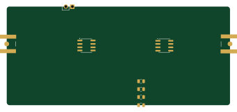
LVDS.recovered.2026-09-26 152659
85 × 37.5 mm9 parts2LNo license1
Similar boards
 AVR/Arduino
V4
stuartpittaway
30 × 50 mm38 parts2LCC-BY-NC-4.01.1k AVR/Arduino
ModuleV450
30 × 61.4 mm39 parts2LCC-BY-NC-4.01.1k AVR/Arduino
Easyduino Atmega
Hanqaqa
68.8 × 53.6 mm35 parts4LCERN-OHL-P-2.0746 AVR/Arduino
Easyduino Atmega Nano
43.4 × 18 mm30 parts4LCERN-OHL-P-2.0746 AVR/Arduino
UsbGpib
xyphro
54 × 15 mm21 parts2LMIT683 AVR/Arduino
Lumberjack
peej
284.7 × 94.2 mm149 parts2LMIT402