
Program counter and adder logic

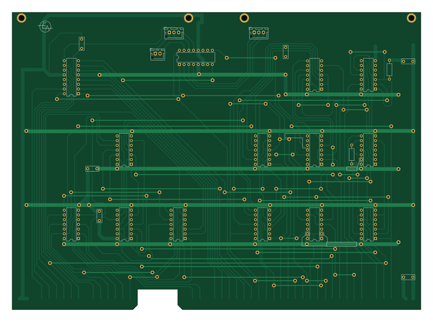
About the Program counter and adder logic PCB
Program counter and adder logic is an open source PCB design by ibm2030, published on GitHub. It is a 2-layer board measuring 220 × 160 mm, with 29 components from 22 distinct parts.
Other key parts include the 74LS05, 74LS07, 74LS00, DM9602 and 74LS20. By type, the board carries 14 ICs, 6 capacitors, 5 connectors and 2 resistors.
From the project
EDUC-8 recreation by Gwyllym Suter
Main components on the Program counter and adder logic
Program counter and adder logic bill of materials (BOM)
29 components, 22 distinct parts — part numbers from the project's BOM.
| Qty | Part | Footprint | Refs |
|---|---|---|---|
| 2 | 74LS05 7496 | DIP-16_W7.62mm | U1, U2 |
| 1 | 74LS05 74LS10 | DIP-14_W7.62mm | U3 |
| 1 | 74LS07 9001 | DIP-14_W7.62mm | U4 |
| 1 | 74LS07 74LS10 | DIP-14_W7.62mm | U5 |
| 1 | 74LS00 7400 | DIP-14_W7.62mm | U6 |
| 2 | 74LS05 7400 | DIP-14_W7.62mm | U7, U11 |
| 1 | 74LS00 7480 | DIP-14_W7.62mm | U8 |
| 2 | 74LS00 74LS04 | DIP-14_W7.62mm | U9, U12 |
| 1 | DM9602 7400 | DIP-14_W7.62mm | U10 |
| 1 | 74LS20 | DIP-14_W7.62mm | U13 |
| 1 | 74LS01 | DIP-14_W7.62mm | U14 |
| 1 | 32-way-pcb-edge-Educ-8-connectors | PCB_32pin | J1 |
| 1 | Conn_01x03_Male | JST_XH_B3B-XH-AM_1x03_P2.50mm_Vertical | J2 |
| 1 | CONN_01X16_FEMALE Conn_01x03_Male | JST_XH_B3B-XH-AM_1x03_P2.50mm_Vertical | J3 |
| 1 | CONN_01X04_FEMALE Conn_01x02_Male | JST_XH_B2B-XH-AM_1x02_P2.50mm_Vertical | J4 |
| 1 | CONN_01X04_FEMALE 16-way-pcb-edge-Educ-8-connectors | PCB_16pin | J5 |
| 2 | Card_handle | Card_handle | H1, H2 |
| 3 | 100NF 47nF | C_Disc_D7.0mm_W2.5mm_P5.00mm | C1, C5, C6 |
| 1 | 47UF 47nF | C_Disc_D7.0mm_W2.5mm_P5.00mm | C2 |
| 1 | 1NF 47nF | C_Disc_D7.0mm_W2.5mm_P5.00mm | C3 |
Show 2 more
| Qty | Part | Footprint | Refs |
|---|---|---|---|
| 1 | 100PF 47nF | C_Disc_D7.0mm_W2.5mm_P5.00mm | C4 |
| 2 | 180R 2k2 | R_Axial_DIN0207_L6.3mm_D2.5mm_P10.16mm_Horizontal | R1, R2 |
Program counter and adder logic design files
The KiCad project lives in the ibm2030/EDUC8 repository on GitHub; these links point at the commit this page was built from.
Program counter and adder logic: common questions
How big is the Program counter and adder logic PCB?
The Program counter and adder logic measures 220 × 160 mm, has 2 copper layers and is 1.6 mm thick.
How many components are on the Program counter and adder logic?
29 components, from 22 distinct parts, with part numbers taken from the project's own BOM. The full bill of materials is listed on this page.
Where can I download the Program counter and adder logic design files?
From the ibm2030/EDUC8 repository on GitHub, which has the KiCad layout, the schematic and the BOM; the links under Design files point to each one.
Can I use the Program counter and adder logic design in my own project?
The repository has no license, so all rights stay with ibm2030. Use it as a reference, and ask the author before reusing the design.
More boards in EDUC8
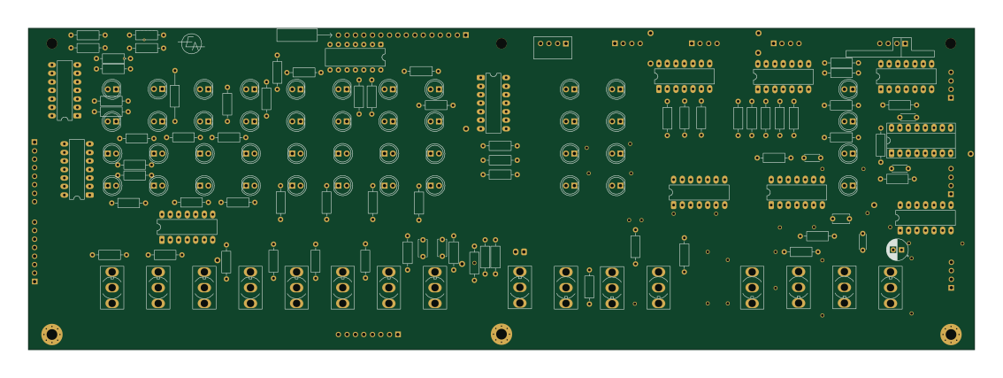
Front panel 9602
283 × 96 mm157 parts2LNo license13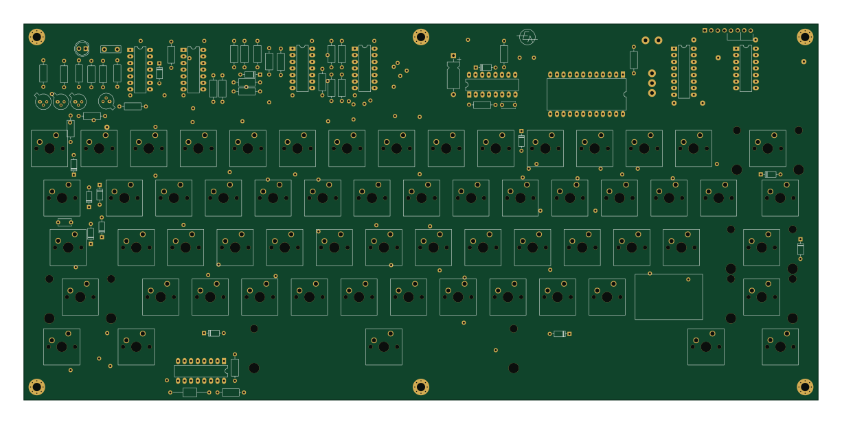
ASCII keyboard
306 × 145 mm124 parts2LNo license13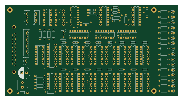
128 X 16 RAM V4 FINAL
180 × 95 mm108 parts4LNo license13
ASCII keyboard 3
297 × 145 mm77 parts2LNo license13
Octal display
140 × 100 mm69 parts2LNo license13
Educ 8 timing
220 × 159.9 mm45 parts4LNo license13
Motherboard
283 × 96 mm44 parts2LNo license13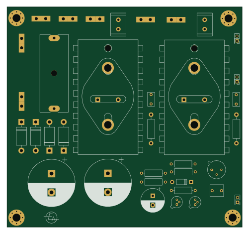
EDUC-8 PSU
125 × 116.8 mm36 parts2LNo license13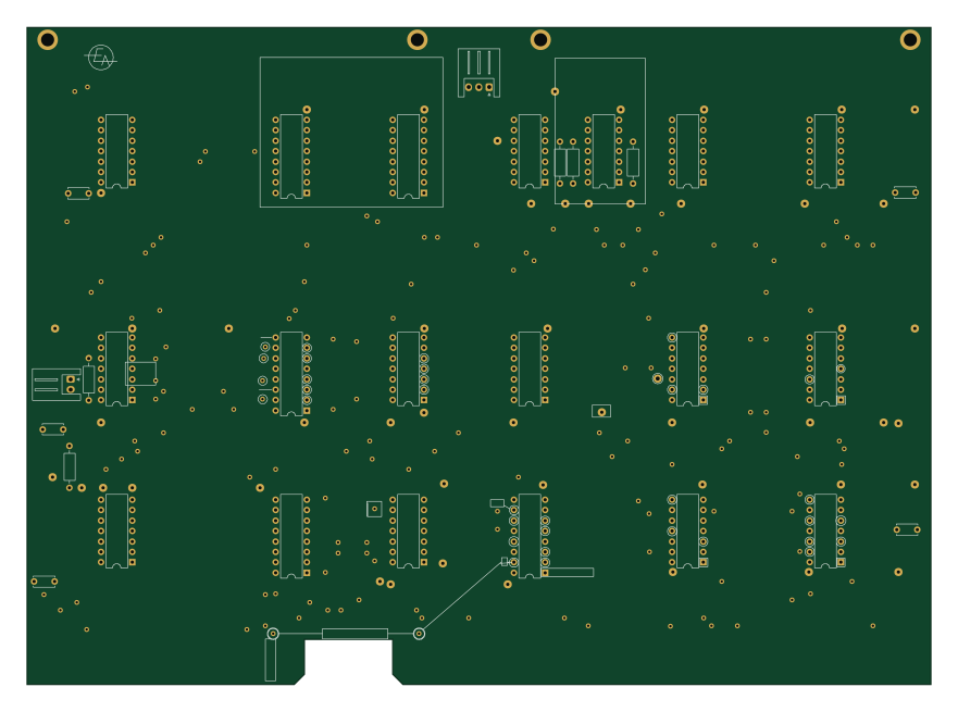
256 word memory
220 × 160 mm36 parts2LNo license13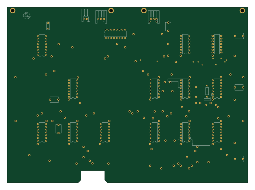
PC and ADDER 74LS74 MOD
220 × 160 mm28 parts2LNo license13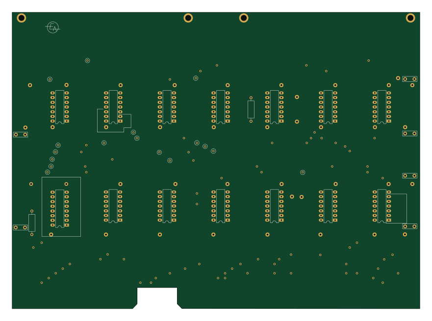
Educ 8 decoder
220 × 160 mm26 parts2LNo license13