
Instruction decoder

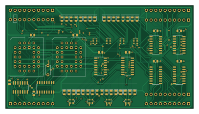
About the Instruction decoder PCB
Instruction decoder is an open source PCB design by ifilot, published on GitHub under the CERN-OHL-S-2.0 license. It is a 2-layer board measuring 101.6 × 55.9 mm, with 68 components from 47 distinct parts.
Other key parts include the 74HC161, SST39SF040, 74HC00 and 74HC238. By type, the board carries 32 diodes, 11 capacitors, 10 ICs, 8 resistors and 7 connectors.
From the project
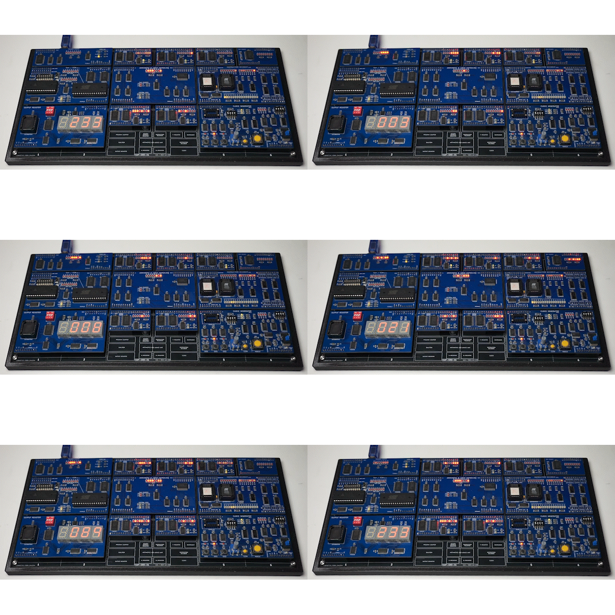
Modular 8-bit computer built with TTL logic units to create a "Simple as Possible" system
This project showcases the design and construction of a modular 8-bit computer built with TTL logic units. The core principle behind the project is to create a "Simple as Possible" system, focusing on simplicity, modularity, and compactness.
- TTL Logic-Based Design: The computer is built using traditional TTL (Transistor-Transistor Logic) components, adhering to a fundamental, hands-on approach to computing. - Modular Architecture: Designed for modularity, each functional unit (ALU, registers, memory, control logic, etc.) is implemented as a separate module, allowing for easy debugging…
Main components on the Instruction decoder
Instruction decoder bill of materials (BOM)
68 components, 47 distinct parts.
| Qty | Part | Footprint | Refs |
|---|---|---|---|
| 1 | 74HC161 | SO-16_3.9x9.9mm_P1.27mm | U1 |
| 2 | SST39SF040 | PLCC-32_THT-Socket | U2, U6 |
| 1 | 74HC00 | SO-14_3.9x8.65mm_P1.27mm | U3 |
| 6 | 74HC238 | SO-16_3.9x9.9mm_P1.27mm | U4, U5, U7, U8, U9, U10 |
| 1 | INSTRUCTION | PinHeader_1x10_P2.54mm_Vertical | J1 |
| 1 | PARALLEL CONTROL LINES | PinHeader_1x10_P2.54mm_Vertical | J2 |
| 1 | ORTHOGONAL CONTROL LINES 1A | PinHeader_1x10_P2.54mm_Vertical | J3 |
| 1 | ORTHOGONAL CONTROL LINES 1B | PinHeader_1x10_P2.54mm_Vertical | J4 |
| 1 | ORTHOGONAL CONTROL LINES 2A | PinHeader_1x10_P2.54mm_Vertical | J5 |
| 1 | ORTHOGONAL CONTROL LINES 2B | PinHeader_1x10_P2.54mm_Vertical | J6 |
| 1 | CONTROL LINES | PinHeader_1x10_P2.54mm_Vertical | J7 |
| 1 | T0 | LED_0805_2012Metric | D1 |
| 1 | T1 | LED_0805_2012Metric | D2 |
| 1 | T2 | LED_0805_2012Metric | D3 |
| 1 | T3 | LED_0805_2012Metric | D4 |
| 1 | T4 | LED_0805_2012Metric | D5 |
| 1 | T5 | LED_0805_2012Metric | D6 |
| 1 | T6 | LED_0805_2012Metric | D7 |
| 1 | T7 | LED_0805_2012Metric | D8 |
| 1 | T8 | LED_0805_2012Metric | D9 |
Show 27 more
| Qty | Part | Footprint | Refs |
|---|---|---|---|
| 1 | T9 | LED_0805_2012Metric | D10 |
| 1 | T10 | LED_0805_2012Metric | D11 |
| 1 | T11 | LED_0805_2012Metric | D12 |
| 1 | T12 | LED_0805_2012Metric | D13 |
| 1 | T13 | LED_0805_2012Metric | D14 |
| 1 | T14 | LED_0805_2012Metric | D15 |
| 1 | T15 | LED_0805_2012Metric | D16 |
| 1 | PCL0 | LED_0805_2012Metric | D17 |
| 1 | PCL1 | LED_0805_2012Metric | D18 |
| 1 | PCL2 | LED_0805_2012Metric | D19 |
| 1 | PCL3 | LED_0805_2012Metric | D20 |
| 1 | OCLA0 | LED_0805_2012Metric | D21 |
| 1 | OCLA1 | LED_0805_2012Metric | D22 |
| 1 | OCLA2 | LED_0805_2012Metric | D23 |
| 1 | OCLA3 | LED_0805_2012Metric | D24 |
| 1 | PCL4 | LED_0805_2012Metric | D25 |
| 1 | PCL5 | LED_0805_2012Metric | D26 |
| 1 | PCL6 | LED_0805_2012Metric | D27 |
| 1 | PCL7 | LED_0805_2012Metric | D28 |
| 1 | OCLB0 | LED_0805_2012Metric | D29 |
| 1 | OCLB1 | LED_0805_2012Metric | D30 |
| 1 | OCLB2 | LED_0805_2012Metric | D31 |
| 1 | OCLB3 | LED_0805_2012Metric | D32 |
| 10 | C | C_0805_2012Metric | C1, C2, C3, C4, C5, C6, C7, C8 +2 |
| 1 | .1uF | C_Disc_D5.0mm_W2.5mm_P5.00mm | C11 |
| 4 | 330 | R_Array_Convex_4x0603 | RN1, RN2, RN3, RN4 |
| 4 | 220 | R_Array_Convex_4x0603 | RN5, RN6, RN7, RN8 |
Instruction decoder design files
The KiCad project lives in the ifilot/sap-smd repository on GitHub; these links point at the commit this page was built from.
Instruction decoder: common questions
How big is the Instruction decoder PCB?
The Instruction decoder measures 101.6 × 55.9 mm, has 2 copper layers and is 1.6 mm thick.
How many components are on the Instruction decoder?
68 components, from 47 distinct parts. The full bill of materials is listed on this page.
Where can I download the Instruction decoder design files?
From the ifilot/sap-smd repository on GitHub, which has the KiCad layout and the schematic; the links under Design files point to each one.
Can I use the Instruction decoder design in my own project?
Yes, under the terms of its CERN-OHL-S-2.0 license, which ifilot chose for the repository.
More boards in sap-smd
Clock
101.6 × 55.9 mm72 parts2LCERN-OHL-S-2.02
Alu advanced
101.6 × 55.9 mm51 parts2LCERN-OHL-S-2.02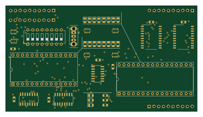
Ramrom
101.6 × 55.9 mm48 parts2LCERN-OHL-S-2.02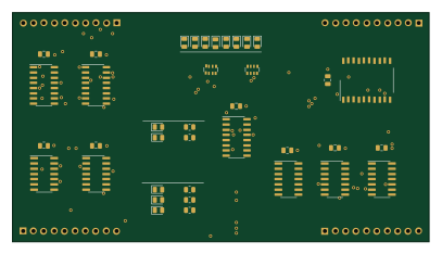
Alu
101.6 × 55.9 mm42 parts2LCERN-OHL-S-2.02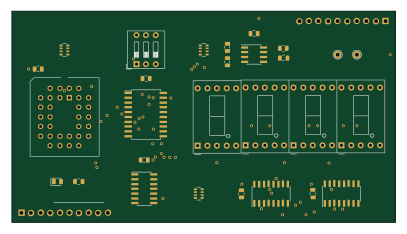
Output register
101.6 × 55.9 mm30 parts2LCERN-OHL-S-2.02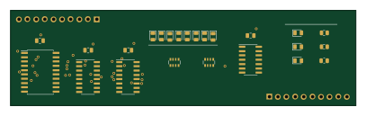
Program counter
101.6 × 27.9 mm26 parts2LCERN-OHL-S-2.02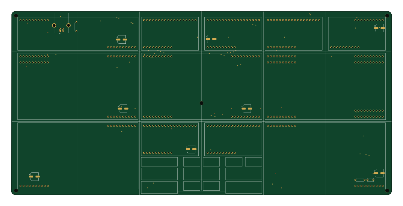
Bp leanplate
319.9 × 154.4 mm24 parts2LCERN-OHL-S-2.02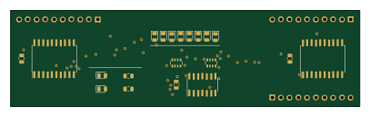
General purpose registers
101.6 × 27.9 mm23 parts2LCERN-OHL-S-2.02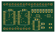
General purpose register halfsize
48.3 × 27.9 mm22 parts2LCERN-OHL-S-2.02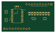
Busreader
48.3 × 27.9 mm16 parts2LCERN-OHL-S-2.02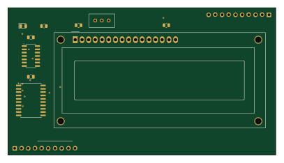
Lcd display
101.6 × 55.9 mm12 parts2LCERN-OHL-S-2.02