
USB JST-XH Converter

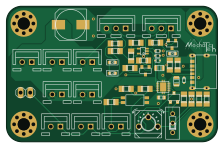
About the USB JST-XH Converter PCB
USB JST-XH Converter is an open source PCB design by issaimaru, published on GitHub under the Apache-2.0 license. It is a 2-layer board measuring 55.9 × 35.9 mm, with 44 components from 29 distinct parts.
Other key parts include the TCKE805NAWSON10B_TOS-REC and TLP293. By type, the board carries 14 resistors, 4 diodes, 4 capacitors, 2 ICs, 2 switches and 1 jumper.
It belongs with the robotics & motion designs in this gallery.
From the project
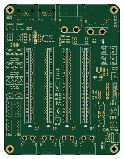
MotorDriver-Controller_v4の機能+αと電源回路を合体させた統合型電源基板
1. DriveUnit Bseriesを使用したいチャネルのカードエッジコネクタに差し込む. 1. モータードライバを差し込んだエッジコネクタと同じチャネルにモータを接続し,必要に応じて同じチャネルのコネクタにロータリーエンコーダを接続する. 1. 非常停止スイッチを刺したコネクタの下にあるトグルスイッチをONに,それ以外のトグルスイッチをOFFにする. 1. XT90とUSB Type-Cからそれぞれ電源を供給し,非常停止スイッチをONにすると稼働する. > Note > USB Type-C用電源を省略する方法はDescriptionsを参照
JP6で信号用の電源をUSB給電or外部給電に切り替えることができます. 外部電源としては,SPOWのピンに接続された電源かリポバッテリーか選ぶことができます. リポバッテリーの場合は「GND」と「SPOW」のピンヘッダを短絡してください. その際にE5VのLEDが点灯していることを確認してください.
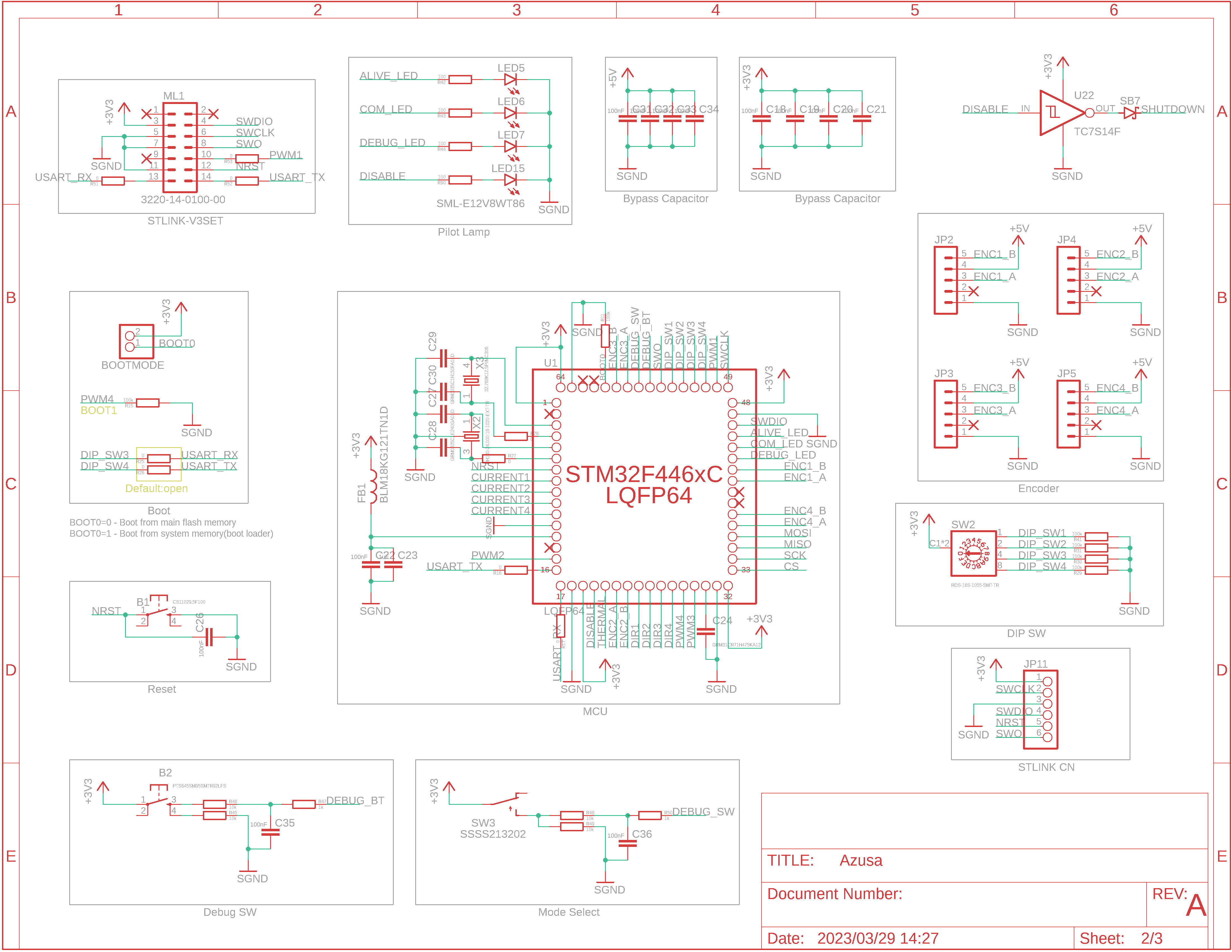
Main components on the USB JST-XH Converter
USB JST-XH Converter bill of materials (BOM)
44 components, 29 distinct parts.
| Qty | Part | Footprint | Refs |
|---|---|---|---|
| 1 | TCKE805NAWSON10B_TOS-REC | WSON10B_TOS-RIC | U1 |
| 1 | TLP293 | SO4_TOS | U2 |
| 1 | MCP6541T-I_LT | SC-70-5 | COMP1 |
| 2 | BSS138 | SOT-23 | FET1, FET2 |
| 4 | MOUNT-HOLE3.2(NORESIST) | 3,2 | H1, H2, H3, H4 |
| 1 | PINHD-1X2 | 1X02 | JP1 |
| 5 | 02-JST | B2B-XH | PORT1, PORT2, PORT3, PORT4, PORT5 |
| 1 | SML-E12V8WT86 | SML-E12V8WT86 | POW1 |
| 1 | SS-12D00G3 | SS-12D00G3 | SW1 |
| 1 | SML-E12V8WT86 | SML-E12V8WT86 | SW2 |
| 1 | GF063PB302K | GF063PB104K | TP1 |
| 1 | 2SC3325 | 2SC3325 | TR1 |
| 1 | UJC-HP-3-SMT-TR | UJC-HP-3-SMT-TR | USB1 |
| 1 | SML-E12V8WT86 | SML-E12V8WT86 | LED1 |
| 3 | RB751S40 | SOD-523 | D1, D3, D4 |
| 1 | PJSD12TS | SOD-523 | D2 |
| 2 | GRM21BC72A105KE01 | GRM21BC72A105KE01 | C1, C2 |
| 1 | GRM1885C1H242JA01D | GRM18 | C3 |
| 1 | UWT1E221MNL1GS | UWT1E221MNL1GS | C4 |
| 2 | RG2012N-101-B-T5 | RG2012 | R1, R2 |
Show 9 more
| Qty | Part | Footprint | Refs |
|---|---|---|---|
| 2 | 5.1k | RG2012 | R3, R4 |
| 1 | 1k | RG2012 | R5 |
| 3 | 10k | RG2012 | R6, R8, R14 |
| 1 | 3k | RG2012 | R7 |
| 1 | 2.7k | RG2012 | R9 |
| 1 | 69.8k | RG2012 | R12 |
| 1 | 75k | RG2012 | R13 |
| 1 | 100k | RG2012 | R16 |
| 1 | 100 | RG2012 | R18 |
USB JST-XH Converter design files
The KiCad project lives in the issaimaru/PowerSupply_v1 repository on GitHub; these links point at the commit this page was built from.
USB JST-XH Converter: common questions
How big is the USB JST-XH Converter PCB?
The USB JST-XH Converter measures 55.9 × 35.9 mm, has 2 copper layers and is 1.6 mm thick.
How many components are on the USB JST-XH Converter?
44 components, from 29 distinct parts. The full bill of materials is listed on this page.
Where can I download the USB JST-XH Converter design files?
From the issaimaru/PowerSupply_v1 repository on GitHub, which has the KiCad layout; the links under Design files point to each one.
Can I use the USB JST-XH Converter design in my own project?
Yes, under the terms of its Apache-2.0 license, which issaimaru chose for the repository.
More boards in PowerSupply_v1
Similar boards

Stack chan
stack-chan
50 × 50 mm33 parts2LApache-2.01.7k
Cube batteryboard
willem-pennings
95 × 95 mm4 parts2LGPL-3.01.1k
Mesabob
rene-dev
87.5 × 50 mm44 parts2LGPL-3.0979
Bob
100 × 100 mm140 parts2LGPL-3.0979
Triple adapter
57 × 75 mm26 parts2LGPL-3.0979
Trollerv2
100 × 75 mm33 parts4LGPL-3.0979