
LiPo Battery Charger

About the LiPo Battery Charger PCB
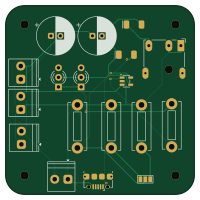
LiPo Battery Charger is an open source PCB design by itsebuka, published on GitHub under the MIT license. It is a 2-layer board measuring 50 × 50 mm, with 18 components from 16 distinct parts.
Other key parts include the Battery controller. By type, the board carries 6 connectors, 4 resistors, 3 diodes, 1 IC, 1 jumper and 1 capacitor.
It belongs with the power & battery, iot & wireless and dev boards & breakouts designs in this gallery.
From the project
This repository contains every single PCB that i have ever designed. The major applications used are Kicad and EasyEDA
A central portfolio repository housing PCB design files, schematic captures, and embedded hardware prototypes. Projects range from custom microcontroller systems to specialized power management boards and discrete logic circuits.
EDA Software: KiCad 10.0 (Schematic Capture, PCB Layout, DRC/ERC) Design Capabilities: Multi-layer PCB routing, power plane isolation, custom footprint creation, DFM (Design for Manufacture). Hardware Domain: Embedded Microcontrollers (ESP32-S3), Power Management Systems, Signal Logic Circuits. Version Control: Git & GitHub Desktop.
Main components on the LiPo Battery Charger
LiPo Battery Charger bill of materials (BOM)
18 components, 16 distinct parts.
| Qty | Part | Footprint | Refs |
|---|---|---|---|
| 1 | Battery controller | SOT-23-5 | U1 |
| 1 | USB_B_Micro | USB_Micro-B_Amphenol_10118194-0001LF_Horizontal | J1 |
| 1 | Screw_Terminal_1 | TerminalBlock_Phoenix_PT-1,5-2-3.5-H_1x02_P3.50mm_Horizontal | J2 |
| 1 | Screw terminal 2 | TerminalBlock_Phoenix_PT-1,5-2-3.5-H_1x02_P3.50mm_Horizontal | J3 |
| 1 | Screw_Terminal_3 | TerminalBlock_Phoenix_PT-1,5-2-3.5-H_1x02_P3.50mm_Horizontal | J4 |
| 1 | Screw_Terminal_4 | TerminalBlock_Phoenix_PT-1,5-2-3.5-H_1x02_P3.50mm_Horizontal | J5 |
| 1 | Barrel_Jack_Switch | BarrelJack_CUI_PJ-079BH_Horizontal | J6 |
| 1 | ~ | CP_Radial_D10.0mm_P2.50mm | 4.7uF1 |
| 1 | SS14 | SMA | 40V,1ADiode1 |
| 1 | SolderJumper | SolderJumper-3_P1.3mm_Bridged123_Pad1.0x1.5mm_NumberLabels | JP1 |
| 2 | Red | LED_D3.0mm-3 | D1, D2 |
| 1 | SS14 | SMA | D3 |
| 1 | ~ | CP_Radial_D10.0mm_P2.50mm | C1 |
| 1 | 330 | R_Bare_Metal_Element_L12.4mm_W4.8mm_P11.40mm | R1 |
| 1 | 2k | R_Bare_Metal_Element_L12.4mm_W4.8mm_P11.40mm | R2 |
| 2 | 10K | R_Bare_Metal_Element_L12.4mm_W4.8mm_P11.40mm | R3, R4 |
LiPo Battery Charger design files
The KiCad project lives in the itsebuka/PCB-Design-Core repository on GitHub; these links point at the commit this page was built from.
LiPo Battery Charger: common questions
How big is the LiPo Battery Charger PCB?
The LiPo Battery Charger measures 50 × 50 mm, has 2 copper layers and is 1.6 mm thick.
How many components are on the LiPo Battery Charger?
18 components, from 16 distinct parts. The full bill of materials is listed on this page.
Where can I download the LiPo Battery Charger design files?
From the itsebuka/PCB-Design-Core repository on GitHub, which has the KiCad layout and the schematic; the links under Design files point to each one.
Can I use the LiPo Battery Charger design in my own project?
Yes, under the terms of its MIT license, which itsebuka chose for the repository.
More boards in PCB-Design-Core
Similar boards

Stack chan
stack-chan
50 × 50 mm33 parts2LApache-2.01.7k
Display Carrier
AxxAxx
35.6 × 58.2 mm5 parts2LGPL-3.01.7k
Breakout 60pin EEC-IV
rusefi
139.7 × 62.2 mm15 parts2LGPL-3.01.2k
Eecv breakout
140.8 × 53.7 mm9 parts4LGPL-3.01.2k
134pin 7-967288-1
139.7 × 73.7 mm38 parts2LGPL-3.01.2k
Breakout 112pin Connector
174 × 58 mm39 parts2LGPL-3.01.2k