
SplitFlap-Control-Board

About the SplitFlap-Control-Board
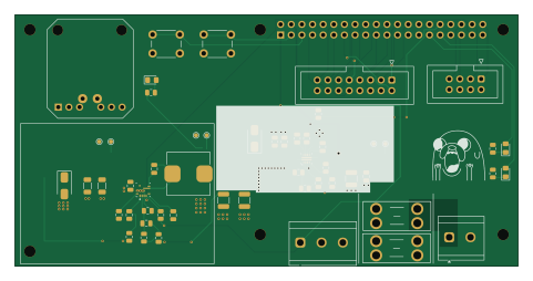
SplitFlap-Control-Board is an open source Raspberry Pi PCB design by itsmeibii, published on GitHub. It is a 2-layer board measuring 120 × 60 mm, with 49 components from 39 distinct parts.
Its main chip is the RASPBERRY_PI_4, from the Raspberry Pi family. Other key parts include the ADAFRUIT_HUSB238_BREAKOUT, TPS56A37RPA and TPS259474ARPW. By type, the board carries 17 resistors, 14 capacitors, 5 connectors, 5 diodes, 3 ICs and 2 fuses.
It belongs with the power & battery and displays & leds designs in this gallery.
From the project
Raspberry Pi 4 control board for a split-flap display + HUB75 LED panels: USB-C PD input, 8A buck, Pi eFuse. KiCad, gerbers, BOM, enclosure.
A Raspberry Pi 4 controller board for a split-flap display with HUB75 LED matrix panels. One USB-C PD cable powers the Pi, the split-flap motor drivers and the LED panels.
The split-flap mechanism and driver boards come from scottbez1/splitflap. This repo contains only the control board and enclosure I designed for it.
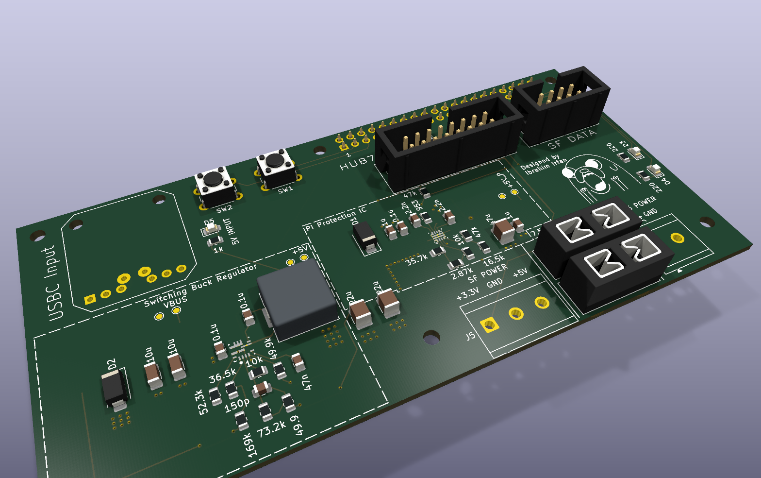
Main components on the SplitFlap-Control-Board
SplitFlap-Control-Board bill of materials (BOM)
49 components, 39 distinct parts — part numbers from the project's BOM.
| Qty | Part | Footprint | Refs |
|---|---|---|---|
| 1 | ADAFRUIT_HUSB238_BREAKOUT Adafruit_HUSB238_Breakout | Adafruit_HUSB238_Breakout | U1 |
| 1 | TPS56A37RPA | Texas_RPA0010A_VQFN-HR-10_3x3mm_P0.5mm | U2 |
| 1 | TPS259474ARPW | Texas_RPW0010A_VQFN-HR-10_2x2mm_P0.475mm | U3 |
| 1 | CONN_02X04_ODD_EVEN Conn_02x04_Odd_Even | IDC-Header_2x04_P2.54mm_Vertical | J1 |
| 1 | CONN_02X08_ODD_EVEN Conn_02x08_Odd_Even | IDC-Header_2x08_P2.54mm_Vertical | J2 |
| 1 | CONN_01X02_PIN Conn_01x02_Pin | TerminalBlock_CUI_TB007-508-02_1x02_P5.08mm_Horizontal | J4 |
| 1 | CONN_01X03_PIN Conn_01x03_Pin | TerminalBlock_CUI_TB007-508-03_1x03_P5.08mm_Horizontal | J5 |
| 1 | RASPBERRY_PI_4 Raspberry_Pi_4 | PinSocket_2x20_P2.54mm_Vertical | J6 |
| 1 | 3568 3A Keystone Electronics | Fuseholder_Blade_Mini_Keystone_3568 | F1 |
| 1 | 3568 7.5A Keystone Electronics | Fuseholder_Blade_Mini_Keystone_3568 | F2 |
| 2 | SW_Push | SW_PUSH_6mm | SW1, SW2 |
| 1 | SMAJ6.0A | D_SMA | D1 |
| 1 | SMAJ22A | D_SMA | D2 |
| 1 | LTST-C170KRKT | LED_0805_2012Metric_Pad1.15x1.40mm_HandSolder | D3 |
| 1 | LTST-C170KGKT | LED_0805_2012Metric_Pad1.15x1.40mm_HandSolder | D4 |
| 1 | LTST-C170TBKT | LED_0805_2012Metric_Pad1.15x1.40mm_HandSolder | D5 |
| 1 | 3.3U 3.3u | L_Wuerth_HCI-1050 | L1 |
| 2 | 10U 10u | C_1206_3216Metric | C1, C2 |
| 3 | 0.1U 0.1u | C_0805_2012Metric | C3, C6, C11 |
| 1 | 47N 47n | C_0805_2012Metric | C4 |
Show 19 more
| Qty | Part | Footprint | Refs |
|---|---|---|---|
| 1 | 150P 150p | C_0805_2012Metric | C5 |
| 2 | 22U 22u | C_1210_3225Metric | C7, C8 |
| 2 | 2.2N 2.2n | C_0805_2012Metric | C9, C12 |
| 2 | 1u | C_0805_2012Metric | C10, C14 |
| 1 | 47U 47u | C_1210_3225Metric | C13 |
| 2 | 220 | R_0805_2012Metric | R1, R11 |
| 1 | 169K 169k | R_0805_2012Metric | R2 |
| 1 | 36.5K 36.5k | R_0805_2012Metric | R3 |
| 1 | 52.3K 52.3k | R_0805_2012Metric | R4 |
| 2 | 10K 10k | R_0805_2012Metric | R5, R14 |
| 1 | 73.2K 73.2k | R_0805_2012Metric | R7 |
| 1 | 49.9 | R_0805_2012Metric | R8 |
| 1 | 49.9K 49.9k | R_0805_2012Metric | R10 |
| 1 | 35.7K 35.7k | R_0805_2012Metric | R12 |
| 1 | 2.87K 2.87k | R_0805_2012Metric | R13 |
| 1 | 953 | R_0805_2012Metric | R15 |
| 2 | 47K 47k | R_0805_2012Metric | R16, R17 |
| 1 | 16.5K 16.5k | R_0805_2012Metric | R18 |
| 1 | 1k | R_0805_2012Metric | R19 |
SplitFlap-Control-Board design files
The KiCad project lives in the itsmeibii/SplitFlap-Control-Board repository on GitHub; these links point at the commit this page was built from.
SplitFlap-Control-Board: common questions
What microcontroller does the SplitFlap-Control-Board use?
The SplitFlap-Control-Board is built around the RASPBERRY_PI_4, from the Raspberry Pi family.
How big is the SplitFlap-Control-Board?
The SplitFlap-Control-Board measures 120 × 60 mm, has 2 copper layers and is 1.6 mm thick.
How many components are on the SplitFlap-Control-Board?
49 components, from 39 distinct parts, with part numbers taken from the project's own BOM. The full bill of materials is listed on this page.
Where can I download the SplitFlap-Control-Board design files?
From the itsmeibii/SplitFlap-Control-Board repository on GitHub, which has the KiCad layout, the schematic and the BOM; the links under Design files point to each one.
Can I use the SplitFlap-Control-Board design in my own project?
The repository has no license, so all rights stay with itsmeibii. Use it as a reference, and ask the author before reusing the design.
Can I test firmware for the SplitFlap-Control-Board without the hardware?
Yes. HardLabs builds a simulation of the board from its netlist and BOM, so you can run and debug Raspberry Pi firmware against it before you order a PCB.
Similar boards
 Raspberry Pi
Open source rover
nasa-jpl
220 × 178 mm144 parts2LApache-2.09.7k Raspberry Pi
Iot
dotnet
56 × 65 mm24 parts2LMIT2.4k Raspberry Pi
SPIRIT
SPIRIT-org
82 × 155 mm130 parts6LCERN-OHL-S-2.01.3k Raspberry Pi
CM5RevEng
schlae
55 × 40 mm417 parts10LNo license1.0k Raspberry Pi
Haxo hw
cardonabits
102.4 × 211.3 mm38 parts2LCustom license672 Raspberry Pi
Phased
Neumi
75 × 100 mm71 parts2LNo license507