
Open source rover

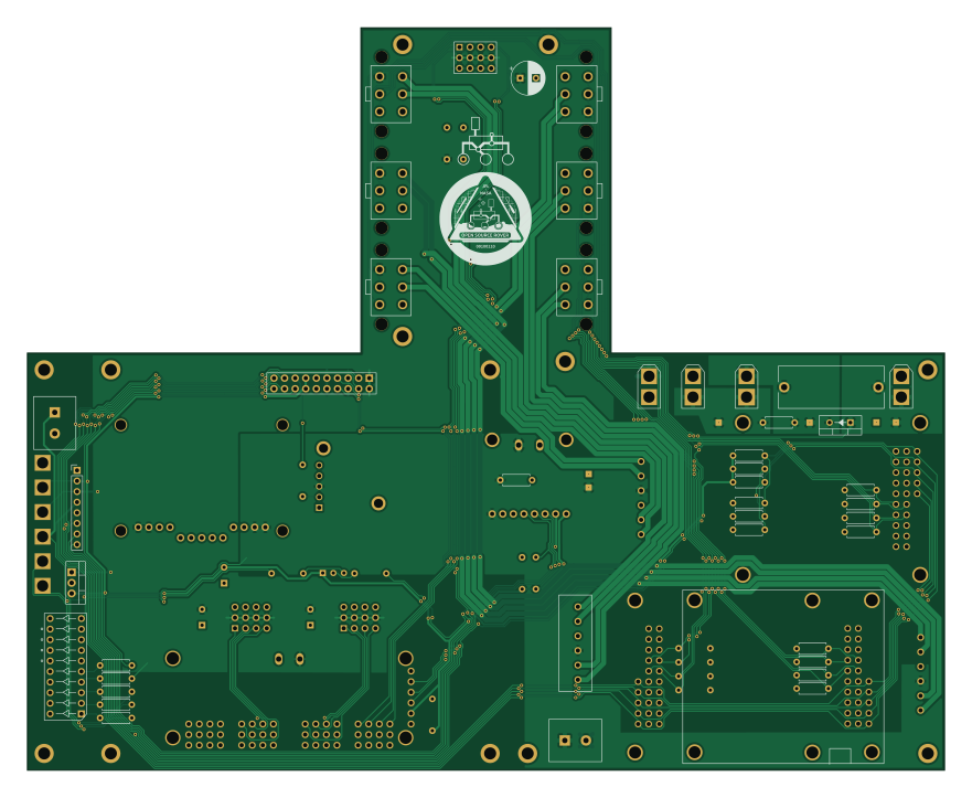
About the Open source rover PCB
Open source rover is an open source Raspberry Pi PCB design by nasa-jpl, published on GitHub under the Apache-2.0 license. It is a 2-layer board measuring 220 × 178 mm, with 144 components from 43 distinct parts.
Its main chip is the Mounting_Holes, from the Raspberry Pi family. Other key parts include the INA260, PCA9685, D24V22F12, D24V150F5 and DC10CGKWA. By type, the board carries 38 resistors, 29 connectors, 23 capacitors, 15 transformers, 7 ICs and 6 transistors.
It belongs with the robotics & motion designs in this gallery.
From the project
A build-it-yourself, 6-wheel rover based on the rovers on Mars!
The overall Control Board consists of a Motor Board with a Brain Board mounted on top. These are the instructions to assemble these two separate pcbs and mount them together as the unified control board.
This document goes through the process of assembling and testing the custom Printed Circuit Boards for the project.
Note that the images in these instructions are taken from an assembly of the v2.0.1 board. There are minimal differences between v2.0.1 and v2.0.3 - such that it wasn't worth doing another photoshoot for v2.0.3. Make sure to follow the written instructions when in doubt.
Main components on the Open source rover
Open source rover bill of materials (BOM)
144 components, 43 distinct parts — part numbers from the project's BOM.
| Qty | Part | Footprint | Refs |
|---|---|---|---|
| 1 | INA260 | INA260 | U1 |
| 1 | PCA9685 | PCA9685_servo_controller | U2 |
| 1 | D24V22F12 D24V22Fx | D24V22Fx_regulator | U3 |
| 1 | D24V150F5 D24V150Fx | D24V150Fx | U4 |
| 2 | DC10CGKWA DC7G3HWA | DC7G3HWA_led_array | U5, U6 |
| 1 | MIC2937A-3.3WT | TO-220-3_Vertical | U7 |
| 1 | Mounting_Holes | raspberry_pi_3b | M1 |
| 6 | 2N3906 | TO-92_Inline_Wide | Q1, Q2, Q3, Q4, Q5, Q6 |
| 2 | XT30-M | AMASS_XT30U-M_1x02_P5.0mm_Vertical | J1, J5 |
| 2 | ED2580 ED2580-ND | ED2580-ND | J2, J6 |
| 2 | XT30-F | AMASS_XT30U-F_1x02_P5.0mm_Vertical | J3, J4 |
| 3 | TSW-104-07-F-T | SSW-104-01-F-T | J7, J12, J19 |
| 6 | MOLEX_172675-0613 Molex_172675-0613 | Molex_172675-0613 | J8, J9, J10, J11, J13, J14 |
| 3 | WM25701 277-11404-ND | 277-11404-ND | J16, J17, J18 |
| 2 | PEC08SAAN | PinHeader_1x08_P2.54mm_Vertical | J20, J30 |
| 1 | PPTC102LFBN-RC | PPTC102LFBN-RC | J21 |
| 2 | S9175-ND_RPI_BREAKOUT S9175-ND_rpi_breakout | S9175-ND | J22, J23 |
| 1 | 6POSHEADER 6posheader | 455-1708-ND | J24 |
| 1 | SSW-104-01-F-T | SSW-104-01-F-T | J25 |
| 1 | WM6548-ND | WM6548-ND | J26 |
Show 23 more
| Qty | Part | Footprint | Refs |
|---|---|---|---|
| 3 | PPTC021LFBN-RC | PPTC021LFBN-RC | J27, J28, J29 |
| 1 | Fuse | 696108003002_5x20_fuseholder | F1 |
| 9 | #4THRU-HOLE | #4THRU-HOLE | MH1, MH2, MH3, MH4, MH5, MH6, MH7, MH8 +1 |
| 8 | brain_board_mounting_hole | brain_board_mounting_hole | MH9, MH10, MH11, MH12, MH13, MH14, MH15, MH16 |
| 3 | RoboClaw | roboclaw_mount | RC1, RC2, RC3 |
| 1 | CT206124 CT206124-ND | CTS-206-124 | SW1 |
| 9 | test_point | test_point | T1, T2, T3, T4, T5, T6, T13, T14 +1 |
| 6 | test_point | test_point_hole | T7, T8, T9, T10, T11, T12 |
| 1 | D | 497-2738-5-ND | D1 |
| 2 | 1N4148 | D_DO-35_SOD27_P7.62mm_Horizontal | D8, D9 |
| 5 | 100NF 100nf | R_Axial_DIN0207_L6.3mm_D2.5mm_P7.62mm_Horizontal | C1, C3, C5, C6, C32 |
| 14 | 10NF 10nf | R_Axial_DIN0207_L6.3mm_D2.5mm_P7.62mm_Horizontal | C2, C4, C9, C10, C13, C14, C15, C16 +6 |
| 1 | 10UF 10uf | CP_Radial_D8.0mm_P3.80mm | C7 |
| 3 | 100UF 100uf | CP_Radial_D8.0mm_P3.80mm | C19, C25, C27 |
| 3 | 1k | R_Axial_DIN0207_L6.3mm_D2.5mm_P7.62mm_Horizontal | R1, R6, R7 |
| 13 | 4.7K 4.7k | R_Axial_DIN0207_L6.3mm_D2.5mm_P7.62mm_Horizontal | R2, R3, R4, R5, R11, R12, R13, R14 +5 |
| 1 | 680 | R_Axial_DIN0207_L6.3mm_D2.5mm_P7.62mm_Horizontal | R8 |
| 1 | 220 | R_Axial_DIN0207_L6.3mm_D2.5mm_P7.62mm_Horizontal | R9 |
| 1 | 100 | R_Axial_DIN0207_L6.3mm_D2.5mm_P7.62mm_Horizontal | R10 |
| 6 | 10K 10k | R_Axial_DIN0207_L6.3mm_D2.5mm_P7.62mm_Horizontal | R15, R16, R17, R36, R37, R38 |
| 6 | 68 | R_Axial_DIN0207_L6.3mm_D2.5mm_P7.62mm_Horizontal | R18, R19, R20, R22, R23, R24 |
| 2 | 0 | R_Axial_DIN0207_L6.3mm_D2.5mm_P7.62mm_Horizontal | R21, R30 |
| 5 | 82 | R_Axial_DIN0207_L6.3mm_D2.5mm_P7.62mm_Horizontal | R25, R26, R27, R28, R29 |
Open source rover design files
The KiCad project lives in the nasa-jpl/open-source-rover repository on GitHub; these links point at the commit this page was built from.
Open source rover: common questions
What microcontroller does the Open source rover use?
The Open source rover is built around the Mounting_Holes, from the Raspberry Pi family.
How big is the Open source rover PCB?
The Open source rover measures 220 × 178 mm, has 2 copper layers and is 1.6 mm thick.
How many components are on the Open source rover?
144 components, from 43 distinct parts, with part numbers taken from the project's own BOM. The full bill of materials is listed on this page.
Where can I download the Open source rover design files?
From the nasa-jpl/open-source-rover repository on GitHub, which has the KiCad layout, the schematic and the BOM; the links under Design files point to each one.
Can I use the Open source rover design in my own project?
Yes, under the terms of its Apache-2.0 license, which nasa-jpl chose for the repository.
Can I test firmware for the Open source rover without the hardware?
Yes. HardLabs builds a simulation of the board from its netlist and BOM, so you can run and debug Raspberry Pi firmware against it before you order a PCB.
Similar boards
 Raspberry Pi
SPIRIT
SPIRIT-org
82 × 155 mm130 parts6LCERN-OHL-S-2.01.3k Raspberry Pi
CM5RevEng
schlae
55 × 40 mm417 parts10LNo license1.0k Raspberry Pi
Haxo hw
cardonabits
102.4 × 211.3 mm38 parts2LCustom license672 Raspberry Pi
PowerBook
BlueSCSI
74.5 × 56.3 mm78 parts2LGPL-3.0449 Raspberry Pi
Desktop 50 Pin TopConn
89.2 × 82.6 mm103 parts2LGPL-3.0449 Raspberry Pi
CanHat
bondus
65 × 30 mm33 parts2LGPL-3.0373