
F91 main board nf

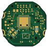
About the F91 main board nf
F91 main board nf is an open source TI MSP430/CC PCB design by jacobl423, published on GitHub under the MIT license. It is a 2-layer board measuring 24.4 × 24.4 mm, with 65 components from 43 distinct parts.
Its main chip is the CC2640(long pads), from the TI MSP430/CC family. Other key parts include the BT_Antenna and 5050660622. By type, the board carries 18 capacitors, 6 resistors, 5 inductors, 3 connectors, 2 ICs and 2 crystals.
It belongs with the displays & leds designs in this gallery.
From the project
updated f91 kepler project
Found here are the PCB files as well as 3D parts that were made to accommodate this project.
My first design for the board used FPC connectors for the display (4 pin) as well as one for programming/debugging (11 pin). This was later changed to use the Molex board to board connector for the display and small connection points across the PCB for programming/debugging. These changes were made to save room and make it easier to not have to solder and unsolder an FPC connector for programming/debugging. The connection points are hard to see in the real images, but are visible in the render seen…

Main components on the F91 main board nf
F91 main board nf bill of materials (BOM)
65 components, 43 distinct parts — part numbers from the project's BOM.
| Qty | Part | Footprint | Refs |
|---|---|---|---|
| 1 | BT_Antenna | BT_ANTENNA | U2 |
| 1 | 5050660622 | 5050660622 | U3 |
| 1 | 32.768kHz | FC-135 | Y1 |
| 1 | 24MHz | TSX-3225 | Y2 |
| 3 | CONN_01X01 | PAD1 | P5, P6, P7 |
| 1 | BLM18HE152SN1 | CAP_0603_FL1 | FL1 |
| 1 | GND | single_probe_point | GND0 |
| 2 | Pad | Pad | Pad1, Pad2 |
| 2 | Pad | Pad_Pad3 | Pad3, Pad4 |
| 1 | Pad | Pad_Pad5 | Pad5 |
| 2 | Pad | Pad_Pad6 | Pad6, Pad7 |
| 1 | N/A DO NOT CONNECT | RES_0402_RESET | RESET0 |
| 1 | SW0 | single_probe_point | SW0 |
| 2 | SingleConnect | SingleConnect | Switch1, Switch2 |
| 1 | SingleConnect | SingleConnect_Switch3 | Switch3 |
| 1 | TDI | single_probe_point | TDI0 |
| 1 | TDO | single_probe_point | TDO0 |
| 1 | CC2640(long pads) | RGZ0048A-VQFN-48(longer_pads) | UNK0 |
| 1 | — | dummyfp0 | UNK_HOLE_0 |
| 1 | — | dummyfp1 | UNK_HOLE_1 |
Show 23 more
| Qty | Part | Footprint | Refs |
|---|---|---|---|
| 1 | — | dummyfp2 | UNK_HOLE_2 |
| 1 | — | dummyfp3 | UNK_HOLE_3 |
| 1 | — | dummyfp4 | UNK_HOLE_4 |
| 1 | — | dummyfp5 | UNK_HOLE_5 |
| 1 | WMCU_RESET | single_probe_point_WMCU_RESET | WMCU_RESET0 |
| 1 | WMCU_RXD | single_probe_point | WMCU_RXD0 |
| 1 | single_probe point | single_probe_point | WMCU_TCK0 |
| 1 | WMCU_TMS | single_probe_point | WMCU_TMS0 |
| 1 | WMCU_TXD | single_probe_point_WMCU_TXD | WMCU_TXD0 |
| 1 | WMCU_VDD | single_probe_point | WMCU_VDD0 |
| 1 | 10uH | IND_0805 | L1 |
| 2 | 2.4nH | IND_0402 | L11, L21 |
| 2 | 2nH | IND_0402 | L12, L13 |
| 7 | 100nF | CAP_0402 | C3, C4, C5, C7, C9, C16, C20 |
| 2 | 10uF | CAP_0603 | C6, C8 |
| 3 | 1pF | CAP_0402 | C11, C13, C21 |
| 3 | 12pF | CAP_0402 | C17, C18, C24 |
| 1 | 1uF | CAP_0402 | C19 |
| 1 | 6.8pF | CAP_0402 | C31 |
| 1 | 1.8pF | CAP_0402 | C51 |
| 1 | 100k | RES_0402 | R1 |
| 2 | 3.3k | RES_0402 | R2, R3 |
| 3 | 100 | RES_0402 | R4, R5, R6 |
F91 main board nf design files
The KiCad project lives in the jacobl423/F91_Jepler repository on GitHub; these links point at the commit this page was built from.
F91 main board nf: common questions
What microcontroller does the F91 main board nf use?
The F91 main board nf is built around the CC2640(long pads), from the TI MSP430/CC family.
How big is the F91 main board nf?
The F91 main board nf measures 24.4 × 24.4 mm, has 2 copper layers and is 1.6 mm thick.
How many components are on the F91 main board nf?
65 components, from 43 distinct parts, with part numbers taken from the project's own BOM. The full bill of materials is listed on this page.
Where can I download the F91 main board nf design files?
From the jacobl423/F91_Jepler repository on GitHub, which has the KiCad layout and the BOM; the links under Design files point to each one.
Can I use the F91 main board nf design in my own project?
Yes, under the terms of its MIT license, which jacobl423 chose for the repository.
Can I test firmware for the F91 main board nf without the hardware?
Yes. HardLabs builds a simulation of the board from its netlist and BOM, so you can run and debug TI MSP430/CC firmware against it before you order a PCB.
More boards in F91_Jepler


Similar boards
 TI MSP430/CC
Pluto
carrotIndustries
24.4 × 24.4 mm36 parts2LGPL-3.0533 TI MSP430/CC
Apimote
riverloopsec
83.3 × 33.4 mm80 parts4LTAPR-OHL-1.089 TI MSP430/CC
Toniebox
toniebox-reverse-engineering
88 × 102 mm11 parts2LNo license36 TI MSP430/CC
Nsumo hardware
artfulbytes
50 × 65 mm73 parts2LMIT33 TI MSP430/CC
Elektronika-1
BenjaminSoelberg
29.5 × 29.5 mm14 parts4LGPL-3.029 TI MSP430/CC
MSP430 Breadstick - Apple Sauce
upsidedownlabs
18.5 × 65.8 mm31 parts2LCERN-OHL-S-2.021