
Riser

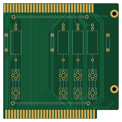
About the Riser PCB
Riser is an open source PCB design by JayesonLS, published on GitHub under the MIT license. It is a 2-layer board measuring 100 × 100 mm, with 11 components from 3 distinct parts.
By type, the board carries 4 fuses, 4 resistors and 3 connectors.
It belongs with the retro computing designs in this gallery.
From the project
ISA Card Designs for Use in Vintage PCs
ISA card designs for use in Vintage PCs.
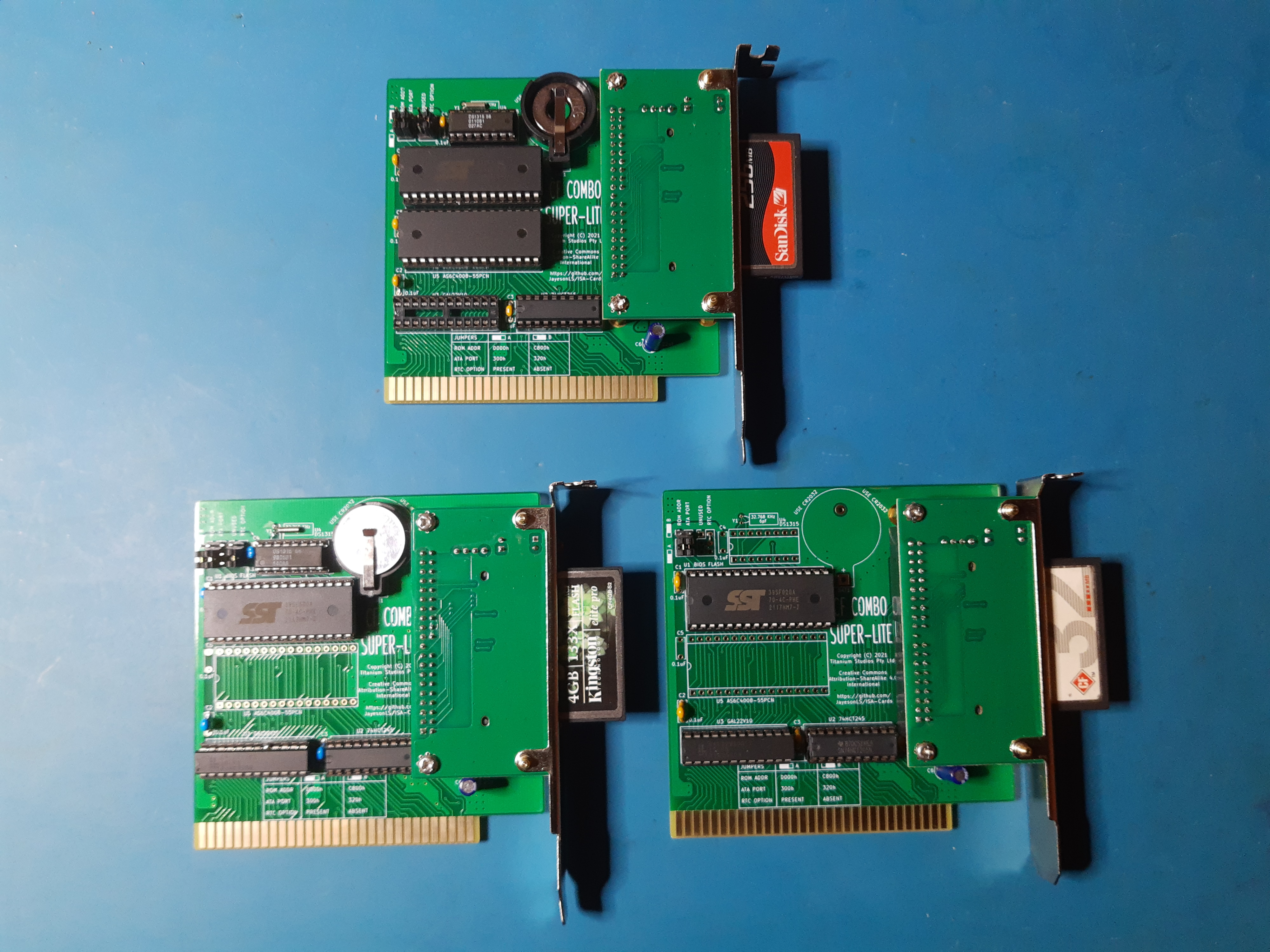
Description: A template from which to build ISA cards. The board dimensions around the edge connector are from an early IBM PC Technical Reference Manual (5150 or 5160). The rear bracket positioning has been measured from an original IBM floppy controller taken from an IBM 5150. This board was an excellent fit when test-fitted in an early Tandy 1000 (25-1000).
Riser bill of materials (BOM)
11 components, 3 distinct parts — part numbers from the project's BOM.
| Qty | Part | Footprint | Refs |
|---|---|---|---|
| 3 | GND Hook | GroundHook | J3, J4, J5 |
| 4 | M205 or bridge | Fuseholder5x20_horiz_open_universal_Type-III | F1, F2, F3, F4 |
| 4 | 10K 0.1R, 1W or bridge | R_Axial_DIN0922_L20.0mm_D9.0mm_P30.48mm_Horizontal | R1, R2, R3, R4 |
Riser design files
The KiCad project lives in the JayesonLS/ISA-Cards repository on GitHub; these links point at the commit this page was built from.
Riser: common questions
How big is the Riser PCB?
The Riser measures 100 × 100 mm, has 2 copper layers and is 1.6 mm thick.
How many components are on the Riser?
11 components, from 3 distinct parts, with part numbers taken from the project's own BOM. The full bill of materials is listed on this page.
Where can I download the Riser design files?
From the JayesonLS/ISA-Cards repository on GitHub, which has the KiCad layout and the BOM; the links under Design files point to each one.
Can I use the Riser design in my own project?
Yes, under the terms of its MIT license, which JayesonLS chose for the repository.
More boards in ISA-Cards
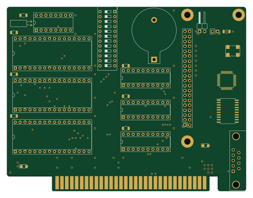
PCSuperCombo
123.3 × 95 mm39 parts2LMIT21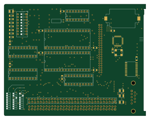
EX-HX-Combo
125.5 × 99 mm37 parts2LMIT21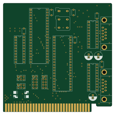
DualSerial
100 × 100 mm21 parts2LMIT21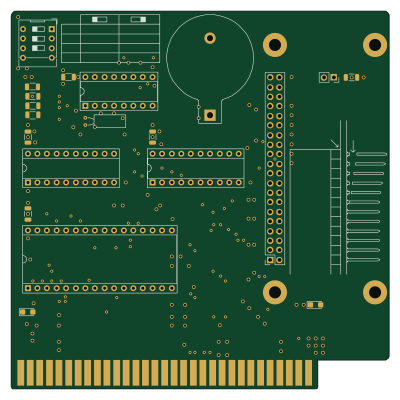
CFSuperLite
100 × 100 mm20 parts2LMIT21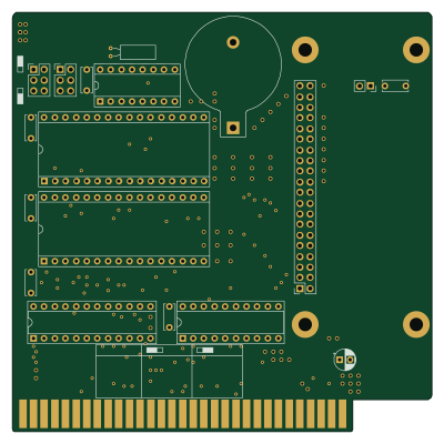
Tandy1000Essentials
100 × 100 mm18 parts2LMIT21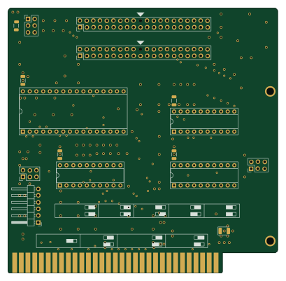
XTA-Interface
102 × 100 mm16 parts2LMIT21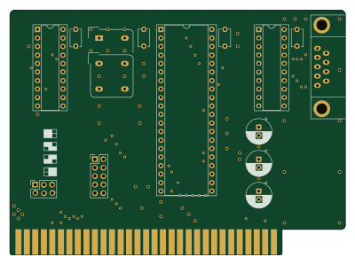
BasicSerial
100 × 73 mm14 parts2LMIT21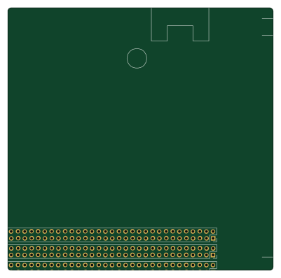
TandyPlusTemplate
100 × 99 mm3 parts2LMIT21
EX-HX-Combo-Backplate
17.5 × 120.2 mm3 parts2LMIT21
Similar boards
Expansion Card Retrofit
FrameworkComputer
24 × 27.3 mm5 parts2LCC-BY-4.01.1k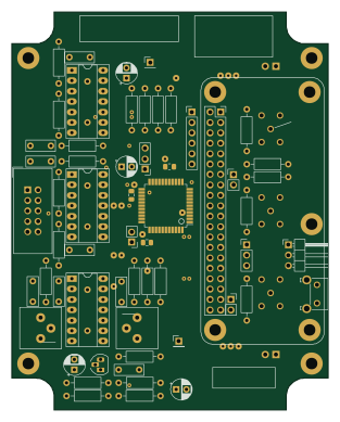
Rgb to hdmi
hoglet67
77 × 97 mm67 parts2LGPL-3.01.0k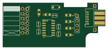
Buffer
53.9 × 23.2 mm13 parts2LGPL-3.01.0k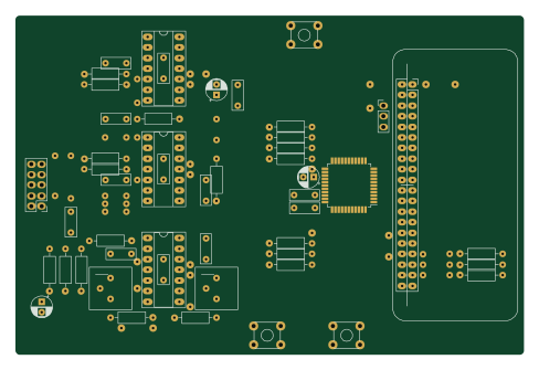
X1
121.9 × 81.3 mm51 parts2LGPL-3.01.0k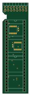
Amiga External
21.9 × 76.7 mm6 parts2LGPL-3.01.0k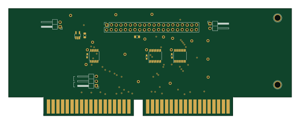
Videoslotadapter
152 × 57.6 mm13 parts2LGPL-3.01.0k