
ME218D-bugger

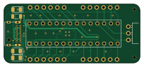
About the ME218D-bugger PCB
ME218D-bugger is an open source PIC PCB design by joaquin-castillo, published on GitHub. It is a 4-layer board measuring 50.8 × 22.2 mm, with 38 components from 19 distinct parts.
Its main chip is the PIC32MX270F256B-I50, from the PIC family. Other key parts include the CP2102N-A02-GQFN24. By type, the board carries 10 capacitors, 10 resistors, 6 connectors, 4 diodes, 3 jumpers and 2 ICs.
It belongs with the usb & debug tools designs in this gallery.
From the project
Design files and documentation for the ME 218 D-bugger. The D-bugger is a tool for ME 218 student students to monitor and visualize the Events and Services Framework.
The fabrication files needed to place an order with JLC are listed below: - IntermediaryrevCfab20221219.zip - IntermediaryrevCjlcbottom.csv - IntermediaryrevC4layer-bottom-pos.csv
If for any reason you need to regenerate the fab files, JLC has some tutorials on How to generate Gerber and Drill files and How to generate the BOM and Centroid file specifically for KiCAD. The BOM and centroid file (aka pick and place file) are used for component assembly. In our experience, getting the centroid file in the right position and orientation relative to the board preview in JLC's quoting tool was a…
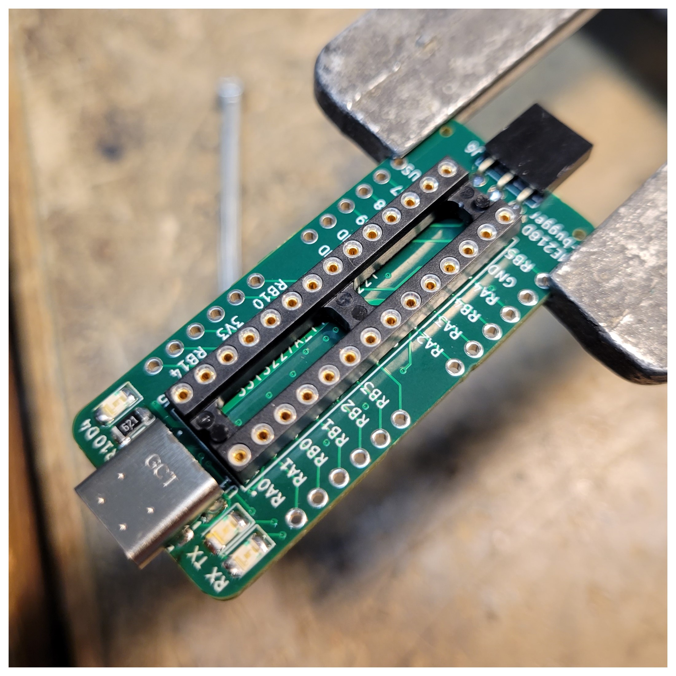
Main components on the ME218D-bugger
ME218D-bugger bill of materials (BOM)
38 components, 19 distinct parts — part numbers from the project's BOM.
| Qty | Part | Footprint | Refs |
|---|---|---|---|
| 1 | CP2102N-A02-GQFN24 | QFN50P400X400X80-25N | IC1 |
| 1 | PIC32MX270F256B-I50 | OST_ED281DT | U1 |
| 4 | Conn_01x06 | PinSocket_1x06_P2.54mm_Vertical | J1, J2, J3, J4 |
| 1 | USB4085-GF-A_REVA4 | GCT_USB4085-GF-A_REVA4 | J5 |
| 1 | Serial_Connector | PinSocket_1x03_P2.54mm_Horizontal | J6 |
| 3 | ToolingHole | JLCPCB_Tooling_Hole | H1, H2, H3 |
| 3 | SolderJumper_3_Open | SolderJumper-3_P2.0mm_Open_TrianglePad1.0x1.5mm_NumberLabels | JP1, JP2, JP3 |
| 2 | LED | LED_1206_3216Metric | D1, D3 |
| 1 | SP0503BAHT | SOT-143 | D2 |
| 1 | GREEN LED | LED_1206_3216Metric | D4 |
| 6 | 0.1uF | C_1206_3216Metric | C1, C2, C4, C5, C8, C9 |
| 3 | 4.7uF | C_1206_3216Metric | C3, C7, C10 |
| 1 | 10uF | C_1206_3216Metric | C6 |
| 2 | 1K | R_1206_3216Metric | R1, R3 |
| 1 | 10K | R_1206_3216Metric | R2 |
| 1 | 22K | R_1206_3216Metric | R4 |
| 1 | 47K | R_1206_3216Metric | R5 |
| 2 | 5.1K | R_1206_3216Metric | R6, R7 |
| 3 | 620 | R_1206_3216Metric | R8, R9, R10 |
ME218D-bugger design files
The KiCad project lives in the joaquin-castillo/ME218D-bugger repository on GitHub; these links point at the commit this page was built from.
ME218D-bugger: common questions
What microcontroller does the ME218D-bugger use?
The ME218D-bugger is built around the PIC32MX270F256B-I50, from the PIC family.
How big is the ME218D-bugger PCB?
The ME218D-bugger measures 50.8 × 22.2 mm, has 4 copper layers and is 1.6 mm thick.
How many components are on the ME218D-bugger?
38 components, from 19 distinct parts, with part numbers taken from the project's own BOM. The full bill of materials is listed on this page.
Where can I download the ME218D-bugger design files?
From the joaquin-castillo/ME218D-bugger repository on GitHub, which has the KiCad layout, the schematic and the BOM; the links under Design files point to each one.
Can I use the ME218D-bugger design in my own project?
The repository has no license, so all rights stay with joaquin-castillo. Use it as a reference, and ask the author before reusing the design.
Can I test firmware for the ME218D-bugger without the hardware?
Yes. HardLabs builds a simulation of the board from its netlist and BOM, so you can run and debug PIC firmware against it before you order a PCB.
Similar boards
 PIC
Pslab hardware
fossasia
99 × 53.3 mm187 parts4LApache-2.01.7k PIC
Lens
ervanalb
80 × 80 mm53 parts4LNo license515 PIC
Micro 8088
skiselev
152.4 × 101.6 mm71 partsGPL-3.0414 PIC
GB-CARTPP-DIY
Gekkio
100 × 100 mm22 parts2LCC-BY-4.0379 PIC
GB-LIVE32
51.4 × 61 mm46 parts4LCC-BY-4.0379 PIC
GB-CART256K-A
51.4 × 61 mm17 parts2LCC-BY-4.0379