
2070-S-100-bus analyzer

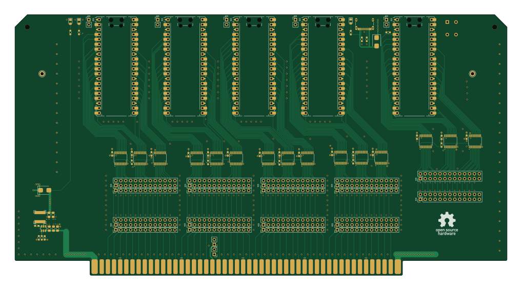
About the 2070-S-100-bus analyzer PCB
2070-S-100-bus analyzer is an open source RP2040/RP2350 PCB design by johnwinans, published on GitHub. It is a 4-layer board measuring 254 × 134.6 mm, with 91 components from 22 distinct parts.
Its main chip is the 2648-SC1631CT-ND, from the RP2040/RP2350 family. Other key parts include the 74LVCH245APW,118 and AP63301WU-7. By type, the board carries 26 connectors, 22 capacitors, 16 ICs, 13 resistors, 5 modules and 5 diodes.
It belongs with the test & measurement designs in this gallery.
From the project
An S-100 bus logic analyzer
This project is based on the open source "gusmanb" Logic Analyzer project from Agustín Gimenez Bernad
I have started a YouTube playlist of videos about this project and my testing of the board.
By using the software from the gusmanb/logicanalyzer repo, a 120 channel logic analyzer can be assembled by installing 5 Raspberry PI PICO boards on this S-100 card and accessed using a USB cables to a PC and/or WiFi as described in the above gusmanb github project Wiki.
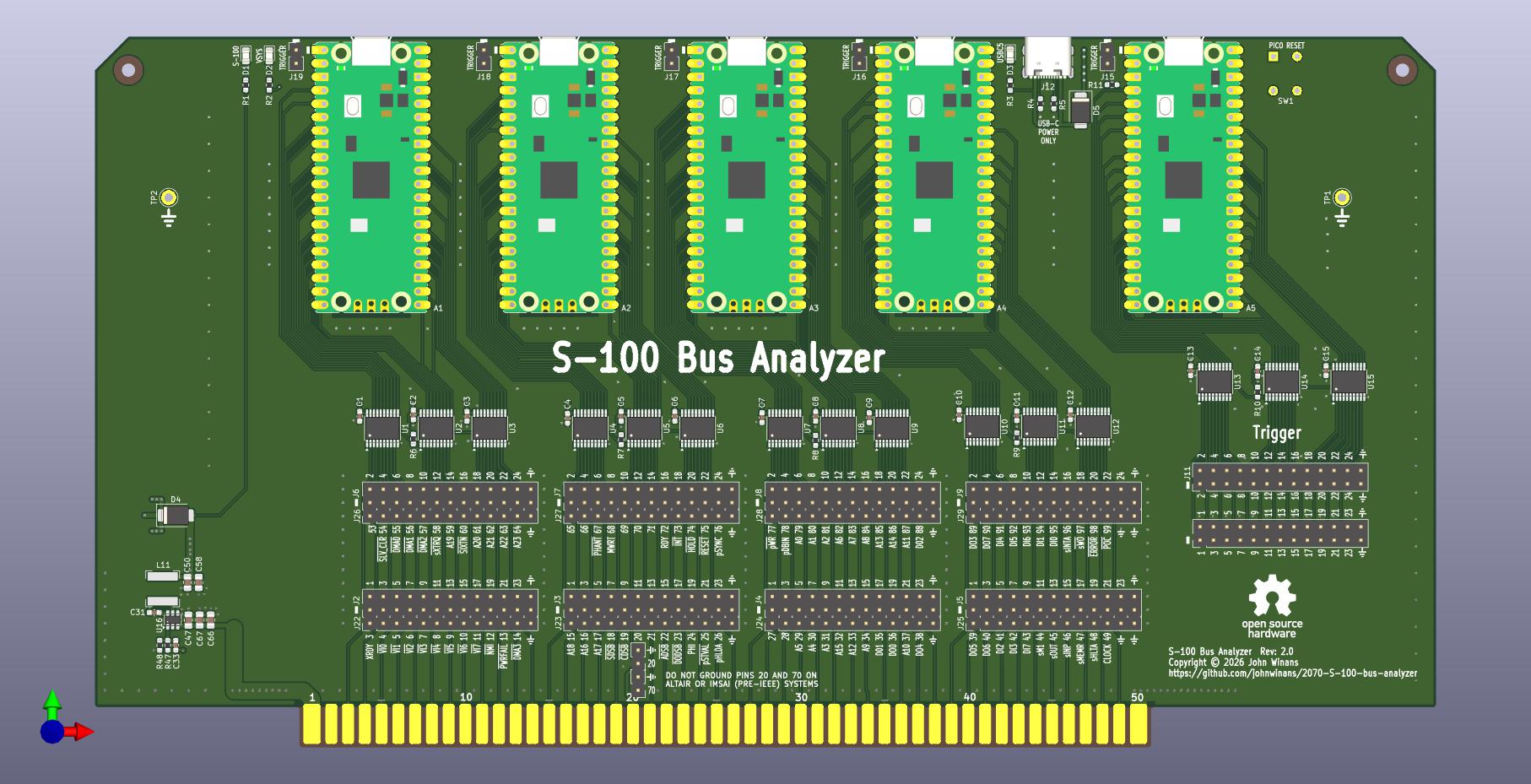
Main components on the 2070-S-100-bus analyzer
2070-S-100-bus analyzer bill of materials (BOM)
91 components, 22 distinct parts — part numbers from the project's BOM.
| Qty | Part | Footprint | Refs |
|---|---|---|---|
| 15 | 74LVCH245APW,118 Nexperia USA Inc. | TSSOP-20_4.4x6.5mm_P0.65mm | U1, U2, U3, U4, U5, U6, U7, U8 +7 |
| 1 | AP63301WU-7 AP63300 Diodes Incorporated | SOT-23-6 | U16 |
| 5 | 2648-SC1631CT-ND RaspberryPi_Pico Raspberry Pi | RaspberryPi_Pico_Common_Unspecified | A1, A2, A3, A4, A5 |
| 10 | CONN_02X13_ODD_EVEN Conn_02x13_Odd_Even | PinHeader_2x13_P2.54mm_Vertical | J2, J3, J4, J5, J6, J7, J8, J9 +2 |
| 1 | USB4105-GF-A GCT | USB_C_Receptacle_GCT_USB4105-xx-A_16P_TopMnt_Horizontal | J12 |
| 7 | CONN_01X02 Conn_01x02 | PinHeader_1x02_P2.54mm_Vertical | J13, J14, J15, J16, J17, J18, J19 |
| 8 | CONN_01X13 Conn_01x13 | PinHeader_1x13_P2.54mm_Vertical | J22, J23, J24, J25, J26, J27, J28, J29 |
| 1 | 1-1825910-5 SW_MEC_5E TE Connectivity ALCOSWITCH Switches | tactile | SW1 |
| 2 | TestPoint | TestPoint_Keystone_5010-5014_Multipurpose | TP1, TP2 |
| 3 | LG R971-KN-1-0-20-R18 LED_Filled ams-OSRAM USA INC. | LED_0805_2012Metric_Pad1.15x1.40mm_HandSolder | D1, D2, D3 |
| 2 | SS56F Shenzhen Slkormicro Semicon Co., Ltd. | D_SMB | D4, D5 |
| 1 | VLS6045EX-6R8M 6.8uH TDK Corporation | L_Bourns-SRN6028 | L11 |
| 16 | C1608X5R1E104K .1uF TDK Corporation | C_0603_1608Metric_Pad1.08x0.95mm_HandSolder | C1, C2, C3, C4, C5, C6, C7, C8 +8 |
| 1 | CL10C470JB8NNNC 47pF Samsung Electro-Mechanics | C_0603_1608Metric_Pad1.08x0.95mm_HandSolder | C33 |
| 1 | TMK212BBJ106KG-T 10uF 25V Taiyo Yuden | C_0805_2012Metric_Pad1.18x1.45mm_HandSolder | C47 |
| 2 | GRM21BR61A226ME44L 22uF Murata Electronics | C_0805_2012Metric_Pad1.18x1.45mm_HandSolder | C50, C58 |
| 2 | C2012X5R1V226M125AC 22uF 35V TDK | C_0805_2012Metric_Pad1.18x1.45mm_HandSolder | C66, C67 |
| 8 | RC0603FR-071KL 1K Yageo | R_0603_1608Metric_Pad0.98x0.95mm_HandSolder | R1, R2, R3, R6, R7, R8, R9, R10 |
| 2 | CR0603-FX-5110ELF 5K1 Bourns Inc. | R_0603_1608Metric_Pad0.98x0.95mm_HandSolder | R4, R5 |
| 1 | RC0603FR-072K2L 2K2 YAGEO | R_0603_1608Metric_Pad0.98x0.95mm_HandSolder | R11 |
Show 2 more
| Qty | Part | Footprint | Refs |
|---|---|---|---|
| 1 | RT0603FRE07158KL 158K YAGEO | R_0603_1608Metric_Pad0.98x0.95mm_HandSolder | R47 |
| 1 | RT0603FRE0730K1L 30K1 YAGEO | R_0603_1608Metric_Pad0.98x0.95mm_HandSolder | R48 |
2070-S-100-bus analyzer design files
The KiCad project lives in the johnwinans/2070-S-100-bus-analyzer repository on GitHub; these links point at the commit this page was built from.
2070-S-100-bus analyzer: common questions
What microcontroller does the 2070-S-100-bus analyzer use?
The 2070-S-100-bus analyzer is built around the 2648-SC1631CT-ND, from the RP2040/RP2350 family.
How big is the 2070-S-100-bus analyzer PCB?
The 2070-S-100-bus analyzer measures 254 × 134.6 mm, has 4 copper layers and is 1.6 mm thick.
How many components are on the 2070-S-100-bus analyzer?
91 components, from 22 distinct parts, with part numbers taken from the project's own BOM. The full bill of materials is listed on this page.
Where can I download the 2070-S-100-bus analyzer design files?
From the johnwinans/2070-S-100-bus-analyzer repository on GitHub, which has the KiCad layout, the schematic and the BOM; the links under Design files point to each one.
Can I use the 2070-S-100-bus analyzer design in my own project?
The repository has no license, so all rights stay with johnwinans. Use it as a reference, and ask the author before reusing the design.
Can I test firmware for the 2070-S-100-bus analyzer without the hardware?
Yes. HardLabs builds a simulation of the board from its netlist and BOM, so you can run and debug RP2040/RP2350 firmware against it before you order a PCB.
Similar boards
 RP2040/RP2350
OSO-BOOK-C1
joeycastillo
85 × 115 mm29 parts2LCC-BY-SA-4.08.1k RP2040/RP2350
Corne cherry
foostan
277.2 × 107.5 mm164 parts2LCC-BY-4.07.7k RP2040/RP2350
Corne chocolate
277.2 × 107.5 mm164 parts2LCC-BY-4.07.7k RP2040/RP2350
Jitx design
gusmanb
55.5 × 65 mm26 parts4LGPL-3.05.0k RP2040/RP2350
LogicAnalyzer
57 × 55.2 mm6 parts2LGPL-3.05.0k RP2040/RP2350
Main
google
98 × 71 mm102 parts2LApache-2.02.9k