
CANFD-Transceiver-Breakout-Board-MCP2562FD

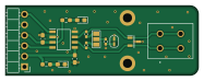
About the CANFD-Transceiver-Breakout-Board-MCP2562FD
CANFD-Transceiver-Breakout-Board-MCP2562FD is an open source PCB design by jonnylin22, published on GitHub. It is a 2-layer board measuring 46.7 × 16.7 mm, with 14 components from 10 distinct parts.
Other key parts include the MCP2562FD-E/SN. By type, the board carries 4 resistors, 3 diodes, 3 capacitors, 1 IC, 1 connector and 1 jumper.
It belongs with the rf & radio and dev boards & breakouts designs in this gallery.
From the project
CANFD Physical Layer Breakout Board
The file named gerbers.zip stores the most up to date generated PCB manufacturing files. The folder named version2-with-JST-PH3/ ustilizes a JST-PH3 connector with the same components.
Main components on the CANFD-Transceiver-Breakout-Board-MCP2562FD
CANFD-Transceiver-Breakout-Board-MCP2562FD bill of materials (BOM)
14 components, 10 distinct parts — part numbers from the project's BOM.
| Qty | Part | Footprint | Refs |
|---|---|---|---|
| 1 | MCP2562FD-E/SN MCP2562FD-E_SN | SOIC127P600X175-8N | U1 |
| 1 | 1862042 | 1862042 | J2 |
| 1 | Jumper_2_Small_Open | SolderJumper-2_P1.3mm_Open_RoundedPad1.0x1.5mm | JP1 |
| 1 | C56816 HEADER_MALE_6X1 | PinHeader_1x06_P2.54mm_Horizontal | K1 |
| 2 | LTST-C191KRKT LED | LED_0603_1608Metric_Pad1.05x0.95mm_HandSolder | D1, D2 |
| 1 | CDSOT23-T24CAN | SOT95P230X117-3N | D3 |
| 2 | CL10E104KC8VPNC 100n | C_0603_1608Metric_Pad1.08x0.95mm_HandSolder | C1, C3 |
| 1 | C0402C472J5RACTU 4.7n | R_0402_1005Metric_Pad0.72x0.64mm_HandSolder | C2 |
| 2 | RC0402FR-0762RL 60R | R_0402_1005Metric_Pad0.72x0.64mm_HandSolder | R1, R2 |
| 2 | RC0603FR-072K2L 2k2 | R_0603_1608Metric_Pad0.98x0.95mm_HandSolder | R3, R4 |
CANFD-Transceiver-Breakout-Board-MCP2562FD design files
The KiCad project lives in the jonnylin22/CANFD-Transceiver-MCP2562FD-Breakout-Board repository on GitHub; these links point at the commit this page was built from.
CANFD-Transceiver-Breakout-Board-MCP2562FD: common questions
How big is the CANFD-Transceiver-Breakout-Board-MCP2562FD?
The CANFD-Transceiver-Breakout-Board-MCP2562FD measures 46.7 × 16.7 mm, has 2 copper layers and is 1.6 mm thick.
How many components are on the CANFD-Transceiver-Breakout-Board-MCP2562FD?
14 components, from 10 distinct parts, with part numbers taken from the project's own BOM. The full bill of materials is listed on this page.
Where can I download the CANFD-Transceiver-Breakout-Board-MCP2562FD design files?
From the jonnylin22/CANFD-Transceiver-MCP2562FD-Breakout-Board repository on GitHub, which has the KiCad layout, the schematic and the BOM; the links under Design files point to each one.
Can I use the CANFD-Transceiver-Breakout-Board-MCP2562FD design in my own project?
The repository has no license, so all rights stay with jonnylin22. Use it as a reference, and ask the author before reusing the design.
More boards in CANFD-Transceiver-MCP2562FD-Breakout-Board
Similar boards
Breakout 112pin Connector
rusefi
174 × 58 mm39 parts2LGPL-3.01.2k
Eecv breakout
140.8 × 53.7 mm9 parts4LGPL-3.01.2k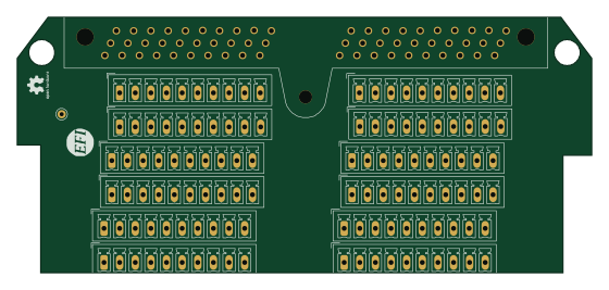
Breakout 60pin EEC-IV
139.7 × 62.2 mm15 parts2LGPL-3.01.2k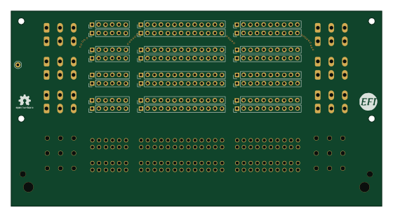
134pin 7-967288-1
139.7 × 73.7 mm38 parts2LGPL-3.01.2k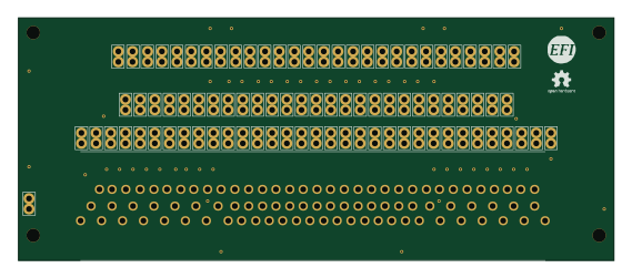
88 Pin Vag Breakout
142 × 58 mm91 parts2LGPL-3.01.2k
Rj45 breakout
rene-dev
15.2 × 53.8 mm3 parts2LGPL-3.0979