
Solar-Smartphone-Charger

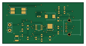
About the Solar-Smartphone-Charger PCB
Solar-Smartphone-Charger is an open source PCB design by JoshuaMularczyk, published on GitHub under the MIT license. It is a 2-layer board measuring 74.5 × 38.1 mm, with 24 components from 24 distinct parts.
Other key parts include the LM3478MA_NOPB. By type, the board carries 11 resistors, 7 capacitors, 1 IC, 1 transistor, 1 connector and 1 diode.
It belongs with the power & battery designs in this gallery, and the repository also holds 5 earlier revisions of it.
From the project
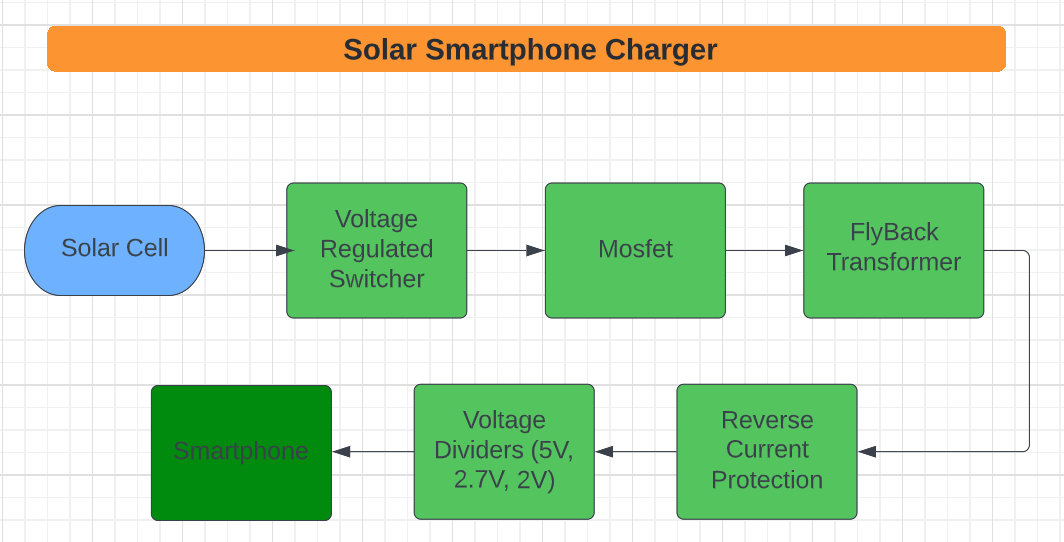
This project applies skills of Power Electronics to create, deign, and construct a solar powered battery charger.
The power electronics project that Christian Williams and I decided on was based around the specifications of new generation iPhone. We knew that Apple is picky with their products, so if we could get it to work with an iPhone it should, in theory, work with Android as well. I decided to use the LM3478 High-Efficiency Low-Side N-Channel Controller for our Switching Regulator. This is the heart of our circuit and allows for a reccomended 2.97-40V input volage and a peak driver output current of 1A. This chip can withstand a typical input current of 2.7A and a max of 3.3A. We used a 5W 12V…
Main components on the Solar-Smartphone-Charger
Solar-Smartphone-Charger bill of materials (BOM)
24 components, 24 distinct parts.
| Qty | Part | Footprint | Refs |
|---|---|---|---|
| 1 | LM3478MA_NOPB | SOIC-8_3.9x4.9mm_P1.27mm | U1 |
| 1 | CSD16410Q5A | TDSON-8-1 | Q1 |
| 1 | USB_A | USB_A_Molex_67643_Horizontal | J1 |
| 1 | Solar_Cell | SIP-2 | SC1 |
| 1 | B340 | D_SMC | D1 |
| 1 | 10u | DRQ | L1 |
| 1 | 10u | C_1812_4532Metric | C1 |
| 1 | 100n | C_0805_2012Metric | C2 |
| 1 | 82n | C_0603_1608Metric | C3 |
| 1 | 200p | C_0805_2012Metric | C4 |
| 1 | 1n | C_0805_2012Metric | C5 |
| 1 | 1u | C_0805_2012Metric | C6 |
| 1 | 47u | C_1206_3216Metric | C7 |
| 1 | 20 | R_0603_1608Metric | R1 |
| 1 | 887 | R_1206_3216Metric | R2 |
| 1 | 51.1k | R_0805_2012Metric | R3 |
| 1 | 100 | R_0805_2012Metric | R4 |
| 1 | 25m | R_1206_3216Metric | R5 |
| 1 | 29.4k | R_0805_2012Metric | R6 |
| 1 | 10k | R_0805_2012Metric | R7 |
Show 4 more
| Qty | Part | Footprint | Refs |
|---|---|---|---|
| 1 | 130k | R_0805_2012Metric | R8 |
| 1 | 160k | R_0805_2012Metric | R9 |
| 1 | 150k | R_0805_2012Metric | R10 |
| 1 | 100k | R_0805_2012Metric | R11 |
Solar-Smartphone-Charger design files
The KiCad project lives in the JoshuaMularczyk/Solar-Smartphone-Charger repository on GitHub; these links point at the commit this page was built from.
Solar-Smartphone-Charger: common questions
How big is the Solar-Smartphone-Charger PCB?
The Solar-Smartphone-Charger measures 74.5 × 38.1 mm, has 2 copper layers and is 1.6 mm thick.
How many components are on the Solar-Smartphone-Charger?
24 components, from 24 distinct parts. The full bill of materials is listed on this page.
Where can I download the Solar-Smartphone-Charger design files?
From the JoshuaMularczyk/Solar-Smartphone-Charger repository on GitHub, which has the KiCad layout and the schematic; the links under Design files point to each one.
Can I use the Solar-Smartphone-Charger design in my own project?
Yes, under the terms of its MIT license, which JoshuaMularczyk chose for the repository.
Earlier revisions in the repo: SolarChargerV6, SolarChargerV5, SolarChargerV4, SolarChargerV3, SolarChargerV2
Similar boards

EinkPDA screen
TalismanDesign
95 × 54 mm27 parts2LApache-2.02.0k
Stack chan
stack-chan
50 × 50 mm33 parts2LApache-2.01.7k
Display Carrier
AxxAxx
35.6 × 58.2 mm5 parts2LGPL-3.01.7k
ProgrammingAdapter
stuartpittaway
10.5 × 83 mm3 parts2LCC-BY-NC-4.01.1k
TemperaturePCB PANEL
116 × 75.5 mm178 parts2LCC-BY-NC-4.01.1k
Module 16S PassiveBalanceAddOn
61 × 74 mm86 parts2LCC-BY-NC-4.01.1k