
Jones

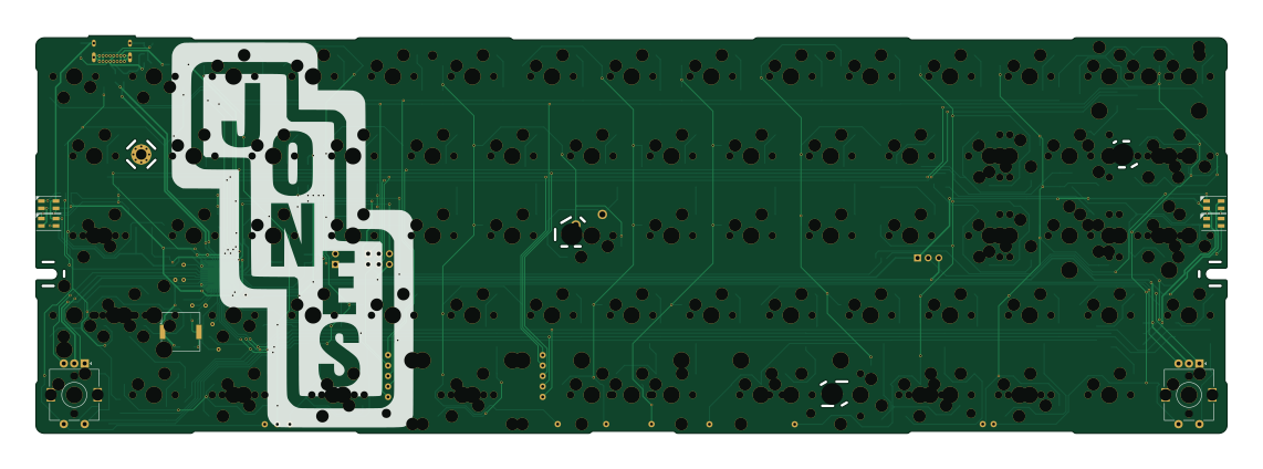
About the Jones PCB
Jones is an open source AVR/Arduino PCB design by jpskenn, published on GitHub under the MIT license. It is a 2-layer board measuring 285 × 95.1 mm, with 211 components from 35 distinct parts.
Its main chip is the ATMEGA32U4-MU, from the AVR/Arduino family. Other key parts include the 24LC64. By type, the board carries 83 diodes, 9 resistors, 7 capacitors, 6 LEDs, 4 connectors and 2 ICs.
It belongs with the keyboards designs in this gallery.
From the project
Row-staggered 60% keyboard with gapless R2-R3 row. GH60 case compatible.
Jones(ジョーンズ)は、2行目と3行目にずれのない、シンメトリカルな60%キーボードです。 左右対象のアルファ部と、右手側Modキーをホームポジションのすぐ隣へ配置したレイアウトが特徴で、自然なポジションで打鍵できます。
40%や50%キーボードのコンパクトで軽快な運指の心地良さと、レイヤーに数字や記号を押し込まなくてよい十分なキー数を兼ね備えています。
GH60型やPoker型に互換性のあるケースや、専用のボトムプレートと組み合わせて使用できます。
遊舎工房とBOOTHで購入できます。 また、その気になればご自分で製造することも可能です。
Jones is a symmetrical 60% keyboard, combined with Ortho-linear and Row-staggered. It has gap-less R2-R3 row. Symmetrical alpha-keys and nearby right side mod-keys provide natural typing position.
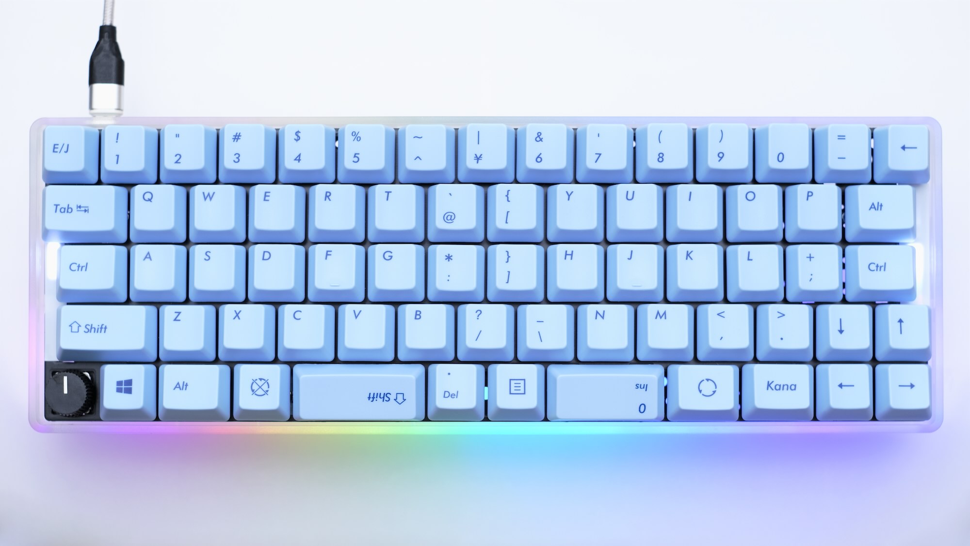
Main components on the Jones
Jones bill of materials (BOM)
211 components, 35 distinct parts — part numbers from the project's BOM.
| Qty | Part | Footprint | Refs |
|---|---|---|---|
| 1 | ATMEGA32U4-MU ATmega32U4-MU | QFN-44-1EP_7x7mm_Pitch0.5mm | U1 |
| 1 | 24LC64 | SO-8_3.9x4.9mm_P1.27mm | U2 |
| 1 | 16MHZ 16MHz | Crystal_SMD_3225-4Pin_3.2x2.5mm_HandSoldering | Y1 |
| 1 | USB_C_RECEPTACLE_USB2.0 USB_C_Receptacle_USB2.0 | USB_C_Receptacle_GCT_USB4085 | J1 |
| 1 | CONN_01X03 Conn_01x03 | PinHeader_1x03_P2.54mm_Vertical | J2 |
| 1 | CONN_01X02 Conn_01x02 | PinHeader_1x02_P2.54mm_Vertical | J3 |
| 1 | CONN_02X03_ODD_EVEN Conn_02x03_Odd_Even | PinHeader_2x03_P2.54mm_Vertical | J5 |
| 1 | 500MA 500mA | Fuse_1206_3216Metric_Pad1.42x1.75mm_HandSolder | F1 |
| 1 | Speaker | Buzzer_Murata_PKMCS0909E4000-R1 | LS1 |
| 1 | 5.2X5.2MM 5.2x5.2mm | SW_SPST_TL3342 | ResetSW1 |
| 67 | SW_Push | MXOnly-1U-Hotswap-guide | SW_0, SW_1, SW_2, SW_3, SW_4, SW_5, SW_6, SW_7 +59 |
| 6 | SW_Push | MXOnly-1.5U-Hotswap-guide | SW_BS1.5u1, SW_CTL1.5u1, SW_ENT1.5u1, SW_LALT1.5u/MHEN1u1, SW_RALT1.5u1, SW_TAB1.5u1 |
| 2 | SW_Push | MXOnly-1.5U-Hotswap-guide-Rotate | SW_BS1.5u2, SW_ENT1.5u2 |
| 8 | SW_Push | MXOnly-1.25U-Hotswap-guide | SW_BS1.25u1, SW_CTL1.25u1, SW_ENT1.25u1, SW_LALT1.25u1, SW_LWIN1.25u1, SW_RALT1.25u1, SW_ROPT1.25u1, SW_narrowRALT1.25u1 |
| 3 | SW_Push | MXOnly-1.25U-Hotswap-guide-Rotate | SW_BS1.25u2, SW_ENT1.25u2, SW_narrowRWIN1.25u1 |
| 1 | SW_Push | MXOnly-2U-Hotswap-guide | SW_BS2u1 |
| 4 | SW_Push | MXOnly-2U-Hotswap-ReversedStabilizers-guide | SW_CSPC2u1, SW_LSFT2u1, SW_LSPC2u1, SW_RSPC2u1 |
| 1 | SW_Push | MXOnly-2.25U-Hotswap-LeftRotate-guide | SW_ENT2.25u1 |
| 1 | SW_Push | MXOnly-1.75U-Hotswap-guide | SW_LSFT1.75u1 |
| 1 | SW_Push | MXOnly-2.25U-Hotswap-guide | SW_LSPC2.25u1 |
Show 15 more
| Qty | Part | Footprint | Refs |
|---|---|---|---|
| 2 | Rotary_Encoder_Switch | RotaryEncoder_Alps_EC11K-Switch_Vertical_H20mm | SW_RE1, SW_RE2 |
| 4 | SK6812MINI | LED_SK6812MINI_PLCC4_3.5x3.5mm_P1.75mm_TriangleMark | LED1, LED2, LED3, LED4 |
| 1 | Conn_01x03 | LED_Strip | LED_STRIP1 |
| 1 | SW_Push | MXOnly-1U-NoLED | SW_;2 |
| 82 | C81598 D | D_SOD-123 | D0, D1, D2, D3, D4, D5, D6, D7 +74 |
| 1 | PRTR5V0U2X | SOT-143 | D10 |
| 1 | 10UF 10uF | C_0805_2012Metric_Pad1.15x1.40mm_HandSolder | C1 |
| 2 | 22PF 22pF | C_0805_2012Metric_Pad1.15x1.40mm_HandSolder | C2, C3 |
| 3 | 0.1UF 0.1uF | C_0805_2012Metric_Pad1.15x1.40mm_HandSolder | C4, C5, C7 |
| 1 | 1UF 1uF | C_0805_2012Metric_Pad1.15x1.40mm_HandSolder | C6 |
| 2 | 5.1K 5.1k | R_0805_2012Metric_Pad1.15x1.40mm_HandSolder | R1, R2 |
| 2 | 22 | R_0805_2012Metric_Pad1.15x1.40mm_HandSolder | R3, R4 |
| 2 | 10K 10k | R_0805_2012Metric_Pad1.15x1.40mm_HandSolder | R5, R6 |
| 1 | 1k | R_0805_2012Metric_Pad1.15x1.40mm_HandSolder | R7 |
| 2 | 4.7K 4.7k | R_0805_2012Metric_Pad1.20x1.40mm_HandSolder | R8, R9 |
Jones design files
The KiCad project lives in the jpskenn/Jones repository on GitHub; these links point at the commit this page was built from.
Jones: common questions
What microcontroller does the Jones use?
The Jones is built around the ATMEGA32U4-MU, from the AVR/Arduino family.
How big is the Jones PCB?
The Jones measures 285 × 95.1 mm, has 2 copper layers and is 1.6 mm thick.
How many components are on the Jones?
211 components, from 35 distinct parts, with part numbers taken from the project's own BOM. The full bill of materials is listed on this page.
Where can I download the Jones design files?
From the jpskenn/Jones repository on GitHub, which has the KiCad layout and the BOM; the links under Design files point to each one.
Can I use the Jones design in my own project?
Yes, under the terms of its MIT license, which jpskenn chose for the repository.
Can I test firmware for the Jones without the hardware?
Yes. HardLabs builds a simulation of the board from its netlist and BOM, so you can run and debug AVR/Arduino firmware against it before you order a PCB.
Similar boards
 AVR/Arduino
Redox keyboard
mattdibi
162.2 × 126.5 mm77 parts2LMIT2.0k AVR/Arduino
ModuleV450
stuartpittaway
30 × 61.4 mm39 parts2LCC-BY-NC-4.01.1k AVR/Arduino
V4
30 × 50 mm38 parts2LCC-BY-NC-4.01.1k AVR/Arduino
Discipline
coseyfannitutti
304.9 × 122.8 mm170 parts2LCC-BY-NC-4.01.0k AVR/Arduino
Megadesk
gcormier
41.7 × 32.2 mm23 parts2LGPL-3.0818 AVR/Arduino
Easyduino Atmega Nano
Hanqaqa
43.4 × 18 mm30 parts4LCERN-OHL-P-2.0746