
RtSolder

About the RtSolder PCB
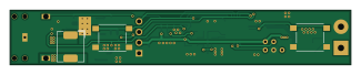
RtSolder is an open source PIC PCB design by juergen4mueller, published on GitHub. It is a 2-layer board measuring 81 × 13 mm, with 44 components from 28 distinct parts.
Its main chip is the PIC16F1788-xML, from the PIC family. Other key parts include the LMR14050SDDAR, MIC5233-3.3YS, OLED_128x32 and TLV333IDCKR. By type, the board carries 17 resistors, 14 capacitors, 5 ICs, 3 connectors, 2 switches and 1 transistor.
From the project
As I have the full Weller power for business I wanted to have a cheap solution to work with Wellers RT solder tips at home. Small package, a wide input voltage range, simple to use and scaleable power consumption have been targets of my project. Final solution is a microchip PIC
As I have the full Weller power for business I wanted to have a cheap solution to work with Wellers RT solder tips at home. Small package, a wide input voltage range, simple to use and scaleable power consumption have been targets of my project. Final solution is a microchip PIC controller, reading the temperature signal which is processed by a TLV333 op amp, controlling a step down converter to regulate temperature and also drive the display. Output power is adjustable in 10W steps from 10W to 40W. In 10W mode its also possible to use USB power. For higher power a higher voltage is…
Main components on the RtSolder
RtSolder bill of materials (BOM)
44 components, 28 distinct parts.
| Qty | Part | Footprint | Refs |
|---|---|---|---|
| 1 | LMR14050SDDAR | TI_SO-PowerPAD-8_ThermalVias | U1 |
| 1 | MIC5233-3.3YS | SOT-223-3_TabPin2 | U2 |
| 1 | PIC16F1788-xML | QFN-28-1EP_6x6mm_P0.65mm_EP4.25x4.25mm | U3 |
| 1 | OLED_128x32 | OLED_128x32 | U4 |
| 1 | TLV333IDCKR | SOT-353_SC-70-5 | U5 |
| 1 | DMP4013LFG-7 | Diodes_PowerDI3333-8 | Q1 |
| 1 | AudioJack3 | JY039-3P | J1 |
| 1 | Conn_01x05 | ICSP_2mm | J2 |
| 1 | Jack-DC | SolderWirePad_1x02_P5.08mm_Drill1.5mm | J3 |
| 2 | Schurter_1301.9319 | SW_Push_1P1T_NO_6x6mm_H9.5mm | SW1, SW2 |
| 1 | PDS760-13 | D_PowerDI-5 | D1 |
| 1 | SRP6540-3R3M | L_Bourns_SRP6540T | L1 |
| 4 | 100nF | C_0603_1608Metric | C1, C5, C10, C13 |
| 4 | 47uF X5R 16V | C_1210_3225Metric | C2, C3, C4, C11 |
| 2 | 10uF X7R 50V | C_1210_3225Metric | C6, C7 |
| 1 | 8n2 | C_0603_1608Metric | C9 |
| 3 | 10n | C_0603_1608Metric | C12, C14, C15 |
| 3 | 4k7 | R_0603_1608Metric | R1, R3, R4 |
| 2 | 10k | R_0603_1608Metric | R2, R12 |
| 1 | 2k2 | R_0603_1608Metric | R5 |
Show 8 more
| Qty | Part | Footprint | Refs |
|---|---|---|---|
| 1 | 2k7 | R_0603_1608Metric | R6 |
| 1 | 18k | R_0603_1608Metric | R8 |
| 3 | 39k | R_0603_1608Metric | R9, R15, R20 |
| 1 | 1k6 | R_0603_1608Metric | R13 |
| 1 | 1M | R_0603_1608Metric | R14 |
| 2 | 5k6 | R_0603_1608Metric | R16, R17 |
| 1 | 10M | R_0603_1608Metric | R18 |
| 1 | 150R | R_0603_1608Metric | R19 |
RtSolder design files
The KiCad project lives in the juergen4mueller/rtSolder repository on GitHub; these links point at the commit this page was built from.
- LayoutPCB/rtSolder.kicad_pcb
- SchematicPCB/rtSolder.kicad_sch
RtSolder: common questions
What microcontroller does the RtSolder use?
The RtSolder is built around the PIC16F1788-xML, from the PIC family.
How big is the RtSolder PCB?
The RtSolder measures 81 × 13 mm, has 2 copper layers and is 1.6 mm thick.
How many components are on the RtSolder?
44 components, from 28 distinct parts. The full bill of materials is listed on this page.
Where can I download the RtSolder design files?
From the juergen4mueller/rtSolder repository on GitHub, which has the KiCad layout and the schematic; the links under Design files point to each one.
Can I use the RtSolder design in my own project?
The repository has no license, so all rights stay with juergen4mueller. Use it as a reference, and ask the author before reusing the design.
Can I test firmware for the RtSolder without the hardware?
Yes. HardLabs builds a simulation of the board from its netlist and BOM, so you can run and debug PIC firmware against it before you order a PCB.
Similar boards
 PIC
Pslab hardware
fossasia
99 × 53.3 mm187 parts4LApache-2.01.7k PIC
Lens
ervanalb
80 × 80 mm53 parts4LNo license515 PIC
Micro 8088
skiselev
152.4 × 101.6 mm71 partsGPL-3.0414 PIC
GB-CARTPP-DIY
Gekkio
100 × 100 mm22 parts2LCC-BY-4.0379 PIC
GB-LIVE32
51.4 × 61 mm46 parts4LCC-BY-4.0379 PIC
GB-CART256K-A
51.4 × 61 mm17 parts2LCC-BY-4.0379