
LT8210-adjustable buck boost regulator

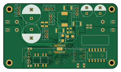
About the LT8210-adjustable buck boost regulator PCB
LT8210-adjustable buck boost regulator is an open source PCB design by Just4Stan, published on GitHub. It is a 4-layer board measuring 98 × 56 mm, with 73 components from 44 distinct parts.
Other key parts include the LT8210EFE. By type, the board carries 26 resistors, 24 capacitors, 8 test points, 6 transistors, 4 switches and 3 diodes.
It belongs with the power & battery designs in this gallery.
From the project
Vin: 4-100V Vout: 5, 9, 12, 15, 20, 24V Iout: 10A (adjustable current limiting)
Main components on the LT8210-adjustable buck boost regulator
LT8210-adjustable buck boost regulator bill of materials (BOM)
73 components, 44 distinct parts.
| Qty | Part | Footprint | Refs |
|---|---|---|---|
| 1 | LT8210EFE | 05-08-1772_ADI-M | U1 |
| 1 | BC547 | TO-92_Inline_Wide_CBE | Q6 |
| 5 | IRFB4615 | TO-220-3_Vertical_GDS | Q7, Q8, Q9, Q10, Q11 |
| 2 | DIP2 | 2DIPCFS | SW2, SW6 |
| 1 | DIP6 | 6DIPCFS | SW3 |
| 1 | 76SD01ST | SW6_76SD01ST_GHL | SW4 |
| 4 | TestPoint | Pin_D1.3mm_L11.0mm | TP1, TP7, TP8, TP21 |
| 4 | ProbePoint | Pin_D1.1mm_L10.2mm_W3.5mm_Flat | TP3, TP4, TP5, TP6 |
| 2 | MURS160 | D_SMB | D2, D3 |
| 1 | LED | LED_D3.0mm | D4 |
| 1 | 7443320680 | IND_1210-WE-HCC_WRE | L1 |
| 1 | 1uF 100v | C_0805_2012Metric | C1 |
| 2 | 22uF 35V | C_1206_3216Metric_Pad1.33x1.80mm_HandSolder | C4, C13 |
| 2 | 220uF 100V | CP_Radial_D16.0mm_P7.50mm | C5, C7 |
| 2 | 10uF 100V | C_1210_3225Metric_Pad1.33x2.70mm_HandSolder | C8, C9 |
| 2 | 220nF | C_0805_2012Metric | C10, C12 |
| 3 | 4.7uF 35v | C_0805_2012Metric | C11, C25, C26 |
| 2 | 470uF 35V | CP_Radial_D10.0mm_P5.00mm | C14, C15 |
| 1 | 2.2uF | C_0805_2012Metric | C16 |
| 1 | 22nF | C_0805_2012Metric | C17 |
Show 24 more
| Qty | Part | Footprint | Refs |
|---|---|---|---|
| 1 | 820pF | C_0805_2012Metric | C18 |
| 1 | 6.8nF | C_0805_2012Metric | C19 |
| 1 | 2.2nF | C_0805_2012Metric | C20 |
| 2 | 1nF | C_0805_2012Metric | C21, C22 |
| 3 | 220pF | C_0805_2012Metric | C23, C24, C27 |
| 2 | 5mOhm | R_2512_6332Metric | R1, R5 |
| 1 | solderBridge | R_2512_6332Metric | R2 |
| 2 | 10R | R_0805_2012Metric_Pad1.20x1.40mm_HandSolder | R6, R7 |
| 2 | 49.9R | R_0805_2012Metric_Pad1.20x1.40mm_HandSolder | R8, R9 |
| 5 | 10k | R_0805_2012Metric_Pad1.20x1.40mm_HandSolder | R10, R16, R18, R35, R36 |
| 1 | 1k | R_0805_2012Metric_Pad1.20x1.40mm_HandSolder | R11 |
| 1 | 220R | R_0805_2012Metric_Pad1.20x1.40mm_HandSolder | R12 |
| 1 | 28k | R_0805_2012Metric_Pad1.20x1.40mm_HandSolder | R13 |
| 1 | 2.61k | R_0805_2012Metric_Pad1.20x1.40mm_HandSolder | R14 |
| 1 | 60.4k | R_0805_2012Metric_Pad1.20x1.40mm_HandSolder | R15 |
| 1 | 2.4k | R_0805_2012Metric_Pad1.20x1.40mm_HandSolder | R17 |
| 1 | 1.2k | R_0805_2012Metric_Pad1.20x1.40mm_HandSolder | R20 |
| 1 | 910R | R_0805_2012Metric_Pad1.20x1.40mm_HandSolder | R21 |
| 1 | 750R | R_0805_2012Metric_Pad1.20x1.40mm_HandSolder | R22 |
| 1 | 510R | R_0805_2012Metric_Pad1.20x1.40mm_HandSolder | R23 |
| 1 | 430R | R_0805_2012Metric_Pad1.20x1.40mm_HandSolder | R24 |
| 1 | 1.5k | R_0805_2012Metric_Pad1.20x1.40mm_HandSolder | R25 |
| 1 | 680R | R_0805_2012Metric_Pad1.20x1.40mm_HandSolder | R26 |
| 1 | 33k | R_0805_2012Metric_Pad1.20x1.40mm_HandSolder | R33 |
LT8210-adjustable buck boost regulator design files
The KiCad project lives in the Just4Stan/LT8210-adjustable-buck-boost-regulator repository on GitHub; these links point at the commit this page was built from.
- LayoutadjustableBuck.kicad_pcb
- SchematicadjustableBuck.kicad_sch
LT8210-adjustable buck boost regulator: common questions
How big is the LT8210-adjustable buck boost regulator PCB?
The LT8210-adjustable buck boost regulator measures 98 × 56 mm, has 4 copper layers and is 1.6 mm thick.
How many components are on the LT8210-adjustable buck boost regulator?
73 components, from 44 distinct parts. The full bill of materials is listed on this page.
Where can I download the LT8210-adjustable buck boost regulator design files?
From the Just4Stan/LT8210-adjustable-buck-boost-regulator repository on GitHub, which has the KiCad layout and the schematic; the links under Design files point to each one.
Can I use the LT8210-adjustable buck boost regulator design in my own project?
The repository has no license, so all rights stay with Just4Stan. Use it as a reference, and ask the author before reusing the design.
Similar boards

EinkPDA screen
TalismanDesign
95 × 54 mm27 parts2LApache-2.02.0k
Stack chan
stack-chan
50 × 50 mm33 parts2LApache-2.01.7k
Display Carrier
AxxAxx
35.6 × 58.2 mm5 parts2LGPL-3.01.7k
ProgrammingAdapter
stuartpittaway
10.5 × 83 mm3 parts2LCC-BY-NC-4.01.1k
TemperaturePCB PANEL
116 × 75.5 mm178 parts2LCC-BY-NC-4.01.1k
Module 16S PassiveBalanceAddOn
61 × 74 mm86 parts2LCC-BY-NC-4.01.1k