
GPIO CTRL
About the GPIO CTRL PCB
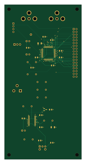
GPIO CTRL is an open source STM32 PCB design by k16shikano, published on GitHub. It is a 4-layer board measuring 70 × 140 mm, with 37 components from 20 distinct parts.
Its main chip is the STM32F401RCT6, from the STM32 family. Other key parts include the LM1117T-3.3, DIR9001PW and MAX809STRG (2.93V). By type, the board carries 19 capacitors, 7 resistors, 6 connectors, 4 ICs and 1 inductor.
From the project
16ビットR-2RラダーによるDAコンバーターの設計
- TOSリンク(S/PDIF)からの44.1kHz入力 - ノンオーバーサンプリング - 左右2チャンネル - カードケージ構成(同一回路を1枚にまとめた SINGLEBOARD` あり)
DACCHANNEL と DACCHANNELAXIAL は同一の電気設計**で、S3 / S5 のどちらにも挿さります。 ラダー抵抗の実装方法だけが違います。
SINGLEBOARD もカードケージと同一の電気設計です。JBP とバックプレーンは無く、 R チャネルは 8xxx 参照(U8001 など)。±VREF はチャネルごとにローカル生成のままです。 信号層は F.Cu / In2.Cu / In3.Cu / B.Cu、In1.Cu と In4.Cu が GND ベタ(ラダー下は抜き)。 JRAW ヘッダ(J401 / J402` およびチャネル側)は基板上配線のタップとして残しています。
Main components on the GPIO CTRL
GPIO CTRL bill of materials (BOM)
37 components, 20 distinct parts — part numbers from the project's BOM.
| Qty | Part | Footprint | Refs |
|---|---|---|---|
| 1 | STM32F401RCT6 | LQFP-64_10x10mm_P0.5mm | U1 |
| 1 | LM1117T-3.3 | TO-220-3_Vertical | U2 |
| 1 | DIR9001PW | TSSOP-28_4.4x9.7mm_P0.65mm | U101 |
| 1 | MAX809STRG (2.93V) | SOT-23 | U102 |
| 1 | 2x18 MALE from 2x PH-1x40SG Akizuki 100167 | Header_2x18_AB_Mating | J2 |
| 1 | SWD 1x4 from PH-1x40SG Akizuki 100167 | PinHeader_1x04_P2.54mm_Vertical | J3 |
| 1 | PLR135/T Akizuki 109595 | PLR135_T10 | J101 |
| 1 | MJ-526-W OUT_L Akizuki 112476 | RCA_RCJ01 | J403 |
| 1 | MJ-526-R OUT_R Akizuki 112475 | RCA_RCJ01 | J404 |
| 1 | MJ-179P 5V CENTER+ Akizuki 100077 | BarrelJack_CUI_PJ-102AH_Horizontal | J701 |
| 1 | 47uH axial L6.3 D2.5 P7.62 | R_Axial_DIN0207_L6.3mm_D2.5mm_P7.62mm_Horizontal | L101 |
| 3 | 10uF 16V tantalum | CP_Radial_Tantal_D4.5mm_P2.50mm | C1, C2, C104 |
| 12 | 100NF 100nF | C_0805_2012Metric | C3, C5, C6, C7, C8, C9, C10, C11 +4 |
| 1 | 4.7UF 4.7uF | C_1206_3216Metric | C4 |
| 1 | 68nF C0G | C_1206_3216Metric | C106 |
| 1 | 4.7nF C0G | C_0805_2012Metric | C107 |
| 1 | 30pF C0G | C_0805_2012Metric | C110 |
| 3 | 10K 10k | R_Axial_DIN0207_L6.3mm_D2.5mm_P7.62mm_Horizontal | R1, R2, R108 |
| 1 | 680 | R_Axial_DIN0207_L6.3mm_D2.5mm_P7.62mm_Horizontal | R102 |
| 3 | 100 | R_Axial_DIN0207_L6.3mm_D2.5mm_P7.62mm_Horizontal | R103, R104, R105 |
GPIO CTRL design files
The KiCad project lives in the k16shikano/r2r-dac repository on GitHub; these links point at the commit this page was built from.
GPIO CTRL: common questions
What microcontroller does the GPIO CTRL use?
The GPIO CTRL is built around the STM32F401RCT6, from the STM32 family.
How big is the GPIO CTRL PCB?
The GPIO CTRL measures 70 × 140 mm, has 4 copper layers and is 1.6 mm thick.
How many components are on the GPIO CTRL?
37 components, from 20 distinct parts, with part numbers taken from the project's own BOM. The full bill of materials is listed on this page.
Where can I download the GPIO CTRL design files?
From the k16shikano/r2r-dac repository on GitHub, which has the KiCad layout and the BOM; the links under Design files point to each one.
Can I use the GPIO CTRL design in my own project?
The repository has no license, so all rights stay with k16shikano. Use it as a reference, and ask the author before reusing the design.
Can I test firmware for the GPIO CTRL without the hardware?
Yes. HardLabs builds a simulation of the board from its netlist and BOM, so you can run and debug STM32 firmware against it before you order a PCB.
More boards in r2r-dac
 Microchip SAM
SINGLE BOARD
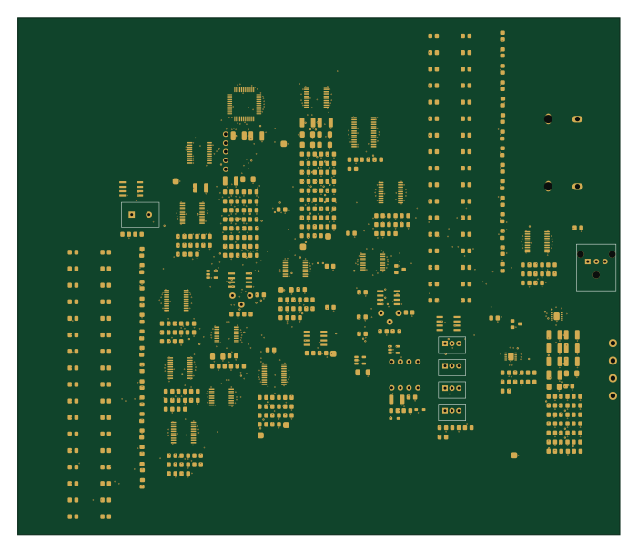
175 × 150 mm349 parts6LNo license0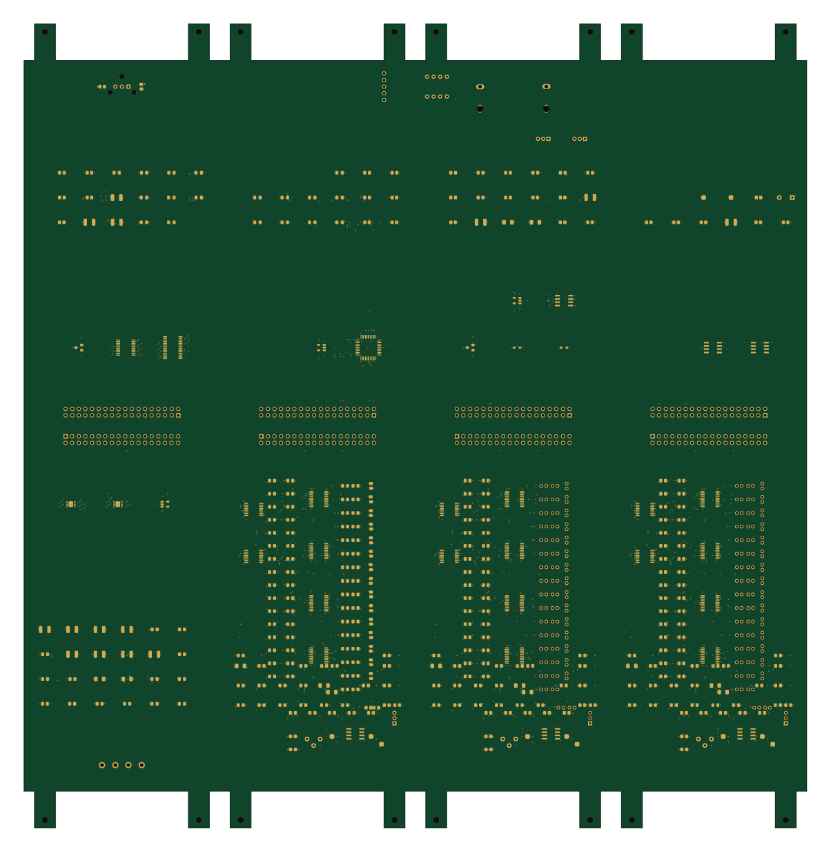 Microchip SAM
PANEL CARDS
300 × 308 mm234 parts4LNo license0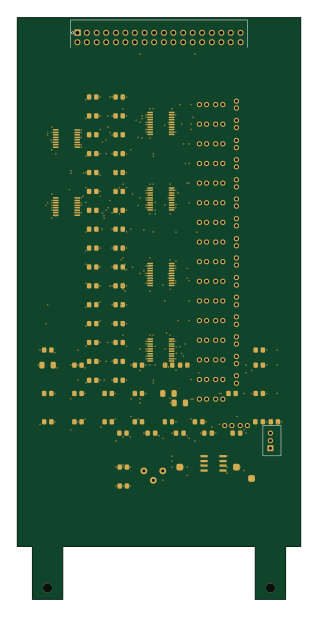
NOS R-2R DAC
75 × 154 mm122 parts4LNo license0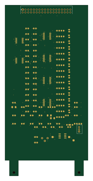
NOS R-2R DAC
75 × 154 mm122 parts4LNo license0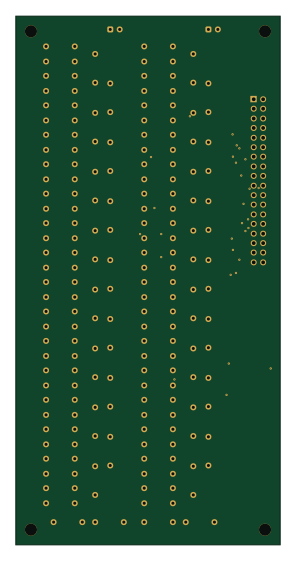
GPIO LADDER
70 × 140 mm101 parts2LNo license0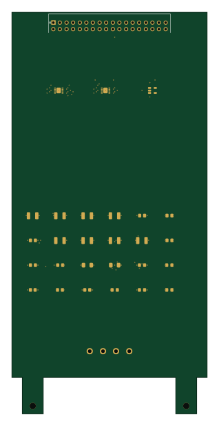
NOS R-2R DAC
75 × 154 mm29 parts4LNo license0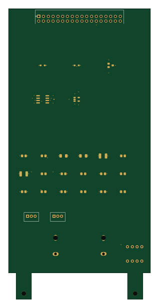
NOS R-2R DAC
75 × 154 mm29 parts4LNo license0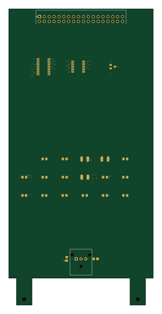
NOS R-2R DAC
75 × 154 mm24 parts4LNo license0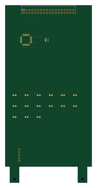 Microchip SAM
NOS R-2R DAC
75 × 154 mm19 parts4LNo license0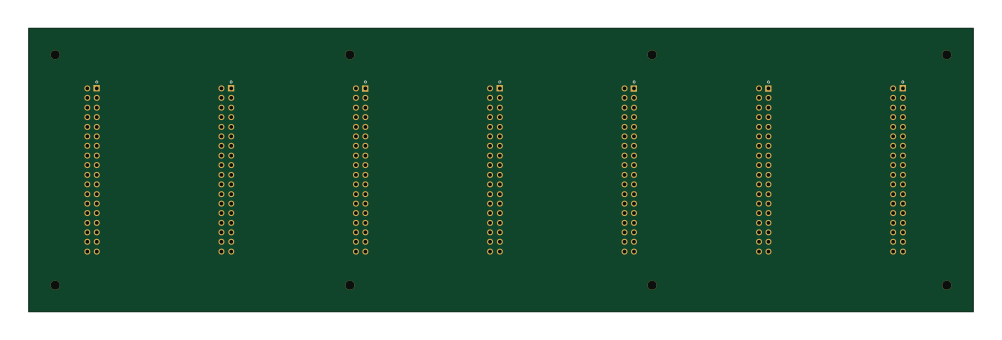
NOS R-2R DAC
250 × 75 mm7 parts4LNo license0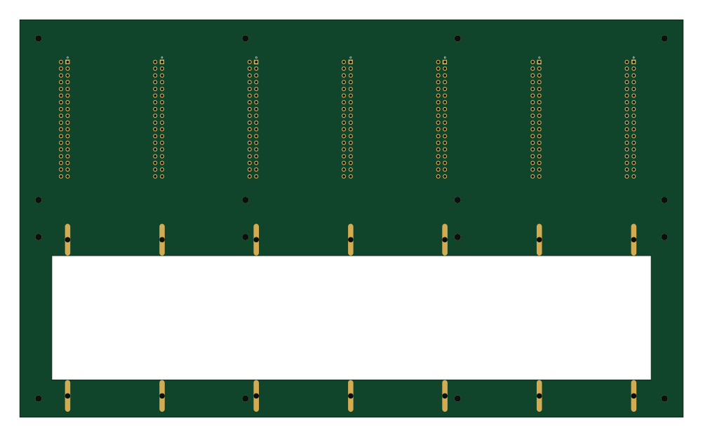
PANEL BACKPLANE
250 × 150 mm7 parts4LNo license0
Similar boards
 STM32
STM32AxxSolder
AxxAxx
39 × 82.5 mm122 parts2LGPL-3.01.7k STM32
STM32AIOC
skuep
21 × 31.5 mm47 parts2LMIT1.4k STM32
STM32Ferris
pierrechevalier83
208.8 × 86.8 mm102 parts2LSHL-2.11.3k STM32
STM32Module 16S
stuartpittaway
71.1 × 89.6 mm113 parts4LCC-BY-NC-4.01.1k STM32
STM32Djinn
tzarc
192.3 × 150.5 mm216 parts2LCERN-OHL-S-2.0988 STM32
STM32Ghoul
228.6 × 79.4 mm163 parts2LCERN-OHL-S-2.0988