
RoboRyo

About the RoboRyo PCB
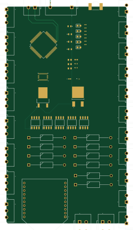
RoboRyo is an open source STM32 PCB design by KaitoTLex, published on GitHub under the MIT license. It is a 4-layer board measuring 64.3 × 115.8 mm, with 68 components from 24 distinct parts.
Its main chip is the STM32F446RETX, from the STM32 family. Other key parts include the XB24CAWIT-001, LD29080DT33R, LD29080DT50R and BNO055. By type, the board carries 10 diodes, 10 capacitors, 8 connectors, 7 resistors, 6 transistors and 5 ICs.
From the project
This is team1280's replacement for the Robo Rio for more redundant and less annoying controls.
The RoboRyo is a more redundant clone of National Intstrument's RoboRio. It provides long range controls and less BS compared to the FRC legal RoboRio. The upside of RoboRyo is that there are more configurable ports compared to the real RoboRyo and it also includes quality of Life features that the real RoboRio dosen't have.
This document gives you an overview of the RoboRyo repository and how it works
Main components on the RoboRyo
RoboRyo bill of materials (BOM)
68 components, 24 distinct parts — part numbers from the project's BOM.
| Qty | Part | Footprint | Refs |
|---|---|---|---|
| 1 | XB24CAWIT-001 | XB24CAWIT001 | IC1 |
| 1 | LD29080DT33R | TO228P972X240-3N | IC2 |
| 1 | LD29080DT50R | LD29080DT50R | IC3 |
| 1 | STM32F446RETX STM32F446RETx | LQFP-64_10x10mm_P0.5mm | U1 |
| 1 | BNO055 | LGA-28_5.2x3.8mm_P0.5mm | U4 |
| 5 | DMG9926USD-13 | SOIC127P600X175-8N | Q1, Q2, Q3, Q4, Q5 |
| 1 | CSD13383F4 | CSD13383F4 | Q7 |
| 8 | 2601-1103/000-004 2601-1103_000-004 | 26011103 | J1, J2, J3, J4, J5, J6, J7, J8 |
| 14 | 2601-1102 | 26011102 | CAN1, DO1, DO2, DO3, DO4, DO5, DO6, DO7 +6 |
| 1 | 2601-1502 | 26011502 | PowerIN1 |
| 1 | APHHS1005SECK | APHHS1005SECK | RSL1 |
| 1 | KSS243GLFG | KSS | S1 |
| 1 | 150060AS75000 | LEDC1608X80N | LED1-A1 |
| 1 | 150060BS75000 | LEDC1608X80N | LED1-B1 |
| 1 | 150060GS75000 | LEDC1608X80N | LED1-G1 |
| 1 | 150060RS75000 | LEDC1608X80N | LED1-R1 |
| 1 | 150060YS75000 | LEDC1608X80N | LED1-Y1 |
| 10 | SB240 | DIOAD1910W86L670D310 | D1, D2, D3, D6, D7, D8, D9, D10 +2 |
| 2 | CL10A475KP8NNNC | CAPC1608X90N | C1, C16 |
| 7 | CL03A104KQ3NNNC | CAPC0603X33N | C2, C3, C4, C5, C6, C9, C13 |
Show 4 more
| Qty | Part | Footprint | Refs |
|---|---|---|---|
| 1 | CL10B105KP8NNNC | CAPC1608X90N | C14 |
| 4 | ERJ3GEYJ102V | ERJ3EKF1000V | R1, R2, R3, R4 |
| 1 | RC1005F103CS | RESC1005X40N | R5 |
| 2 | ERJ-2RKF1001X | ERJ2RKD1004X | R6, R7 |
RoboRyo design files
The KiCad project lives in the KaitoTLex/RoboRyo repository on GitHub; these links point at the commit this page was built from.
RoboRyo: common questions
What microcontroller does the RoboRyo use?
The RoboRyo is built around the STM32F446RETX, from the STM32 family.
How big is the RoboRyo PCB?
The RoboRyo measures 64.3 × 115.8 mm, has 4 copper layers and is 1.6 mm thick.
How many components are on the RoboRyo?
68 components, from 24 distinct parts, with part numbers taken from the project's own BOM. The full bill of materials is listed on this page.
Where can I download the RoboRyo design files?
From the KaitoTLex/RoboRyo repository on GitHub, which has the KiCad layout, the schematic and the BOM; the links under Design files point to each one.
Can I use the RoboRyo design in my own project?
Yes, under the terms of its MIT license, which KaitoTLex chose for the repository.
Can I test firmware for the RoboRyo without the hardware?
Yes. HardLabs builds a simulation of the board from its netlist and BOM, so you can run and debug STM32 firmware against it before you order a PCB.
Similar boards
 STM32
STM32AxxSolder
AxxAxx
39 × 82.5 mm122 parts2LGPL-3.01.7k STM32
STM32AIOC
skuep
21 × 31.5 mm47 parts2LMIT1.4k STM32
STM32Ferris
pierrechevalier83
208.8 × 86.8 mm102 parts2LSHL-2.11.3k STM32
STM32Module 16S
stuartpittaway
71.1 × 89.6 mm113 parts4LCC-BY-NC-4.01.1k STM32
STM32Djinn
tzarc
192.3 × 150.5 mm216 parts2LCERN-OHL-S-2.0988 STM32
STM32Ghoul
228.6 × 79.4 mm163 parts2LCERN-OHL-S-2.0988