
J939-transceiver

About the J939-transceiver PCB
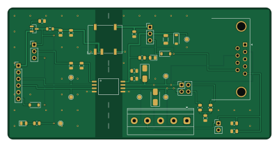
J939-transceiver is an open source PCB design by karimf1, published on GitHub under the MIT license. It is a 2-layer board measuring 100 × 50 mm, with 33 components from 23 distinct parts.
Other key parts include the ISO1042BDWVR and NXE1S0505MC-R7. By type, the board carries 9 capacitors, 7 diodes, 7 resistors, 4 jumpers, 2 ICs and 2 connectors.
It belongs with the rf & radio and dev boards & breakouts designs in this gallery.
From the project
This project is an isolated CAN/J1939 transceiver breakout on a 2-layer board. It includes a DE-9 or terminal block and termination jumper. It demonstrates a complete PCB design workflow: custom symbol/footprint creation, layout, DRC, ordering, hand-soldering, and testing.
A galvanically isolated CAN transceiver on a 100 × 50 mm two-layer board: DE-9 wired to CiA 303-1, a 5-way terminal block carrying the same nets in parallel, split 120 Ω termination on a jumper, and bus-side power generated across the barrier.
The circuit is deliberately trivial — one transceiver, one isolated supply, a connector and two resistors. That is the point. A trivial circuit is the only kind that lets you walk the whole hardware pipeline without the circuit itself becoming the project: a symbol and a footprint drawn by hand from a datasheet, a schematic, a netlist, a board, a…
Main components on the J939-transceiver
J939-transceiver bill of materials (BOM)
33 components, 23 distinct parts — part numbers from the project's BOM.
| Qty | Part | Footprint | Refs |
|---|---|---|---|
| 1 | ISO1042BDWVR Texas Instruments | TI_DWV0008A | U1 |
| 1 | NXE1S0505MC-R7 NXE1S0505MC Murata Power Solutions | Converter_DCDC_Murata_NXExSxxxxMC_SMD | U2 |
| 1 | DMG2301L-7 DMG2301L | SOT-23 | Q1 |
| 1 | Host 1x06 | PinHeader_1x06_P2.54mm_Vertical | J1 |
| 1 | MKDS 1,5/5-5.08 | TerminalBlock_Phoenix_MKDS-1,5-5_1x05_P5.00mm_Horizontal | J3 |
| 1 | VCC1 = 5V / 3V3 | PinHeader_1x03_P2.54mm_Vertical | JP1 |
| 1 | VCC2 = DCDC / bus | PinHeader_1x03_P2.54mm_Vertical | JP2 |
| 1 | TERM 120R | PinHeader_2x02_P2.54mm_Vertical | JP3 |
| 1 | SHLD hard bond | PinHeader_1x02_P2.54mm_Vertical | JP4 |
| 2 | BAT54 | D_SOD-123 | D1, D5 |
| 2 | SMAJ36CA | D_SMA | D2, D6 |
| 2 | green | LED_0805_2012Metric | D3, D4 |
| 1 | 5V6 | D_SOD-123 | D7 |
| 1 | 600R@100MHz | L_0805_2012Metric | FB1 |
| 2 | 4n7 | C_0805_2012Metric | C1, C8 |
| 3 | 100n | C_0805_2012Metric | C2, C4, C9 |
| 1 | 1u | C_0805_2012Metric | C3 |
| 3 | 4u7 | C_0805_2012Metric | C5, C6, C7 |
| 2 | 60R4 1% | R_0805_2012Metric | R1, R2 |
| 2 | 1k5 | R_0805_2012Metric | R3, R6 |
Show 3 more
| Qty | Part | Footprint | Refs |
|---|---|---|---|
| 1 | 100k | R_0805_2012Metric | R4 |
| 1 | 1M | R_0805_2012Metric | R5 |
| 1 | 240R 1% | R_1206_3216Metric | R7 |
J939-transceiver design files
The KiCad project lives in the karimf1/J939-transceiver repository on GitHub; these links point at the commit this page was built from.
- Layoutcan-iso.kicad_pcb
- Schematiccan-iso.kicad_sch
- BOMcan-iso-bom.csv
J939-transceiver: common questions
How big is the J939-transceiver PCB?
The J939-transceiver measures 100 × 50 mm, has 2 copper layers and is 1.6 mm thick.
How many components are on the J939-transceiver?
33 components, from 23 distinct parts, with part numbers taken from the project's own BOM. The full bill of materials is listed on this page.
Where can I download the J939-transceiver design files?
From the karimf1/J939-transceiver repository on GitHub, which has the KiCad layout, the schematic and the BOM; the links under Design files point to each one.
Can I use the J939-transceiver design in my own project?
Yes, under the terms of its MIT license, which karimf1 chose for the repository.
Similar boards
88 Pin Vag Breakout
rusefi
142 × 58 mm91 parts2LGPL-3.01.2k
134pin 7-967288-1
139.7 × 73.7 mm38 parts2LGPL-3.01.2k
Breakout 60pin EEC-IV
139.7 × 62.2 mm15 parts2LGPL-3.01.2k
Breakout 112pin Connector
174 × 58 mm39 parts2LGPL-3.01.2k
Eecv breakout
140.8 × 53.7 mm9 parts4LGPL-3.01.2k
Rj45 breakout
rene-dev
15.2 × 53.8 mm3 parts2LGPL-3.0979