
VWS-SDR

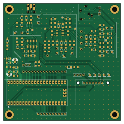
About the VWS-SDR PCB
VWS-SDR is an open source RP2040/RP2350 PCB design by KI3P, published on GitHub under the GPL-3.0 license. It is a 4-layer board measuring 100 × 100 mm, with 103 components from 35 distinct parts.
Its main chip is the SC0915, from the RP2040/RP2350 family. Other key parts include the GALI-S66+, SN74CBTLV3253DR and MC33078DR. By type, the board carries 30 capacitors, 28 resistors, 13 test points, 8 connectors, 6 inductors and 5 ICs.
It belongs with the rf & radio designs in this gallery.
From the project
RF front end for a software defined receiver
This repository contains the files for a 2025 project by the Vienna Wireless Society's Makers Group. This project aims to build the RF front end of a software defined receiver covering the HF bands. The goals of the project are:
1. Learn how to use KiCAD, and 2. Learn surface mount assembly techniques.
The VWS-SDR design draws heavily from the RF board of the T41-EP Software Defined Transceiver (SDT) originally designed by Al Peter-AC8GY and Jack Purdum-W8TEE. The T41-EP is a self-contain SDT that does not require an external PC, laptop, or tablet to use. Al and Jack wrote a book, available…
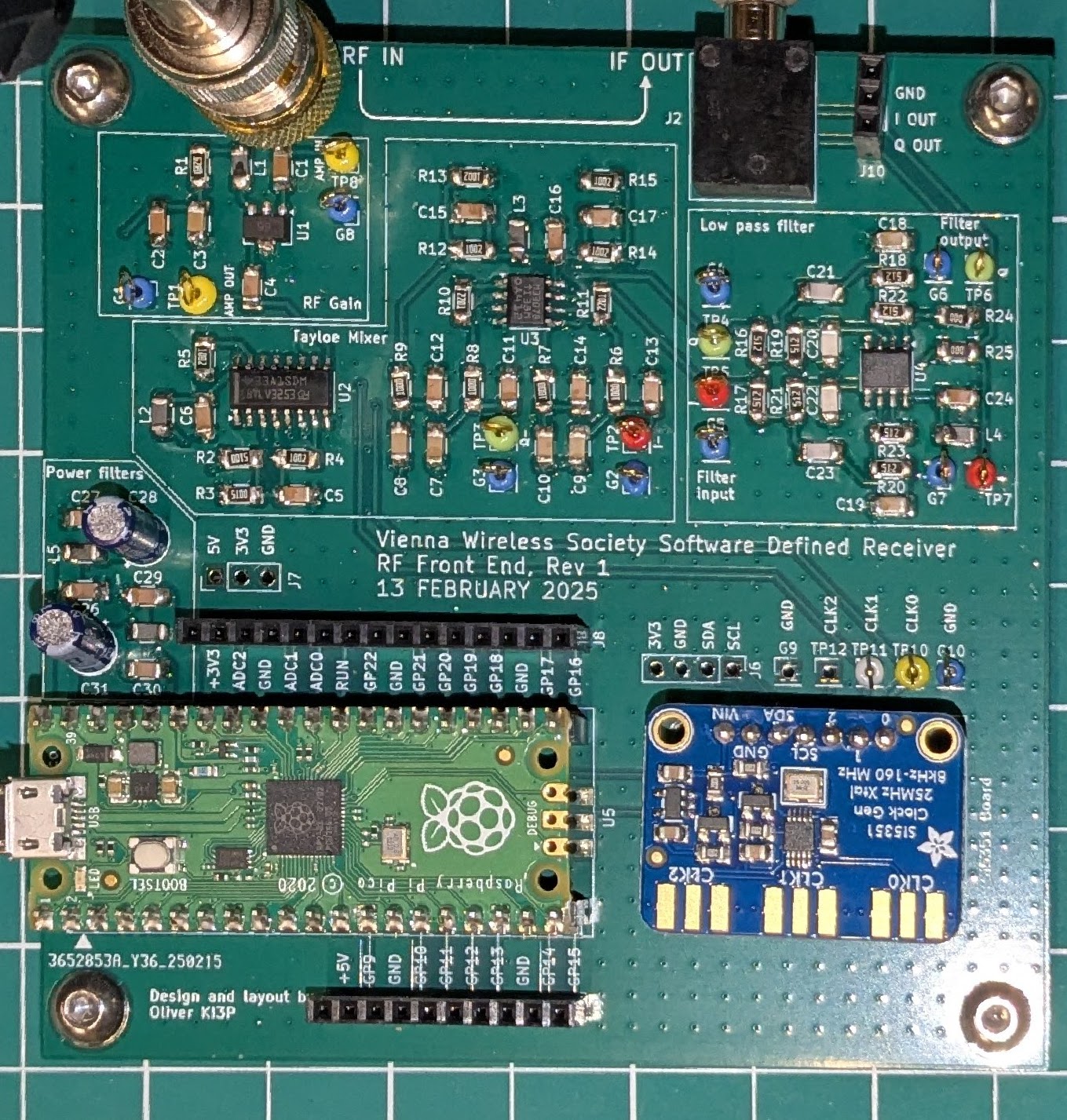
Main components on the VWS-SDR
VWS-SDR bill of materials (BOM)
103 components, 35 distinct parts — part numbers from the project's BOM.
| Qty | Part | Footprint | Refs |
|---|---|---|---|
| 1 | GALI-S66+ GALI-S66 | SOT-89-3 | U1 |
| 1 | SN74CBTLV3253DR 74CBTLV3253DR | SOIC-16_3.9x9.9mm_P1.27mm | U2 |
| 2 | MC33078DR MC33078 | SOIC-8_3.9x4.9mm_P1.27mm | U3, U4 |
| 1 | SC0915 RASPBERRY-PICO | Raspberry_pico_pin_or_castellation_footprint | U5 |
| 1 | CONSMA001-G RF_IN | SMA_Vertical_and_Edgemount | J1 |
| 1 | SJ1-3515N IQ_Out | Jack_3.5mm_STX-3081_Horizontal | J2 |
| 1 | SI5351 board | Adafruit_Si5351 | J3 |
| 1 | I2C breakout | PinHeader_1x04_P2.54mm_Vertical | J6 |
| 1 | Power breakout | PinHeader_1x03_P2.54mm_Vertical | J7 |
| 1 | GPIO Breakout1 | PinSocket_1x15_P2.54mm_Vertical | J8 |
| 1 | GPIO Breakout2 | PinSocket_1x10_P2.54mm_Vertical | J9 |
| 1 | IF breakout | PinSocket_1x03_P2.54mm_Vertical | J10 |
| 10 | TestPoint | PinHeader_1x01_P2.54mm_Vertical | G1, G2, G3, G4, G5, G6, G7, G8 +2 |
| 13 | TestPoint | PinHeader_1x01_P2.54mm_Vertical | TP1/b, TP2, TP3, TP4, TP5, TP6, TP7, TP8 +5 |
| 1 | APTD3216LCGCK 5V LED | LED_1206_3216Metric_Pad1.42x1.75mm_HandSolder | D1 |
| 1 | APTD3216LSYCK 3V3 LED | LED_1206_3216Metric_Pad1.42x1.75mm_HandSolder | D2 |
| 1 | APTD3216LSYCK Indicator | LED_1206_3216Metric_Pad1.42x1.75mm_HandSolder | D3 |
| 1 | LQM31PN1R5M00L 1.5uH | R_1206_3216Metric_Pad1.30x1.75mm_HandSolder | L1 |
| 5 | HZ1206E601R-10 FB | R_1206_3216Metric_Pad1.30x1.75mm_HandSolder | L2, L3, L4, L5, L6 |
| 11 | C1206C104K5RACTU 0.1uF | C_1206_3216Metric_Pad1.33x1.80mm_HandSolder | C1, C2, C4, C5, C6, C15, C16, C17 +3 |
Show 15 more
| Qty | Part | Footprint | Refs |
|---|---|---|---|
| 3 | C1206C106K4PACTU 10uF | C_1206_3216Metric_Pad1.33x1.80mm_HandSolder | C3, C18, C19 |
| 4 | KGM31HR71C105KU 1uF | C_1206_3216Metric_Pad1.33x1.80mm_HandSolder | C7, C8, C9, C10 |
| 6 | C1206C103K5RAC7210 10nF | C_1206_3216Metric_Pad1.33x1.80mm_HandSolder | C11, C12, C13, C14, C26, C29 |
| 2 | KGM31BCG2A181FT 180pF | C_1206_3216Metric_Pad1.33x1.80mm_HandSolder | C20, C22 |
| 2 | C3216C0G2J101G060AA 105pF | C_1206_3216Metric_Pad1.33x1.80mm_HandSolder | C21, C23 |
| 2 | ESK475M016AC3AA 4.7uF | CP_Radial_D5.0mm_P2.00mm | C28, C31 |
| 1 | CR1206-FX-62R0ELF 62R | R_1206_3216Metric_Pad1.30x1.75mm_HandSolder | R1 |
| 2 | CR1206-FX-5100ELF 510R | R_1206_3216Metric_Pad1.30x1.75mm_HandSolder | R2, R3 |
| 6 | CR1206-FX-1002ELF 10k | R_1206_3216Metric_Pad1.30x1.75mm_HandSolder | R4, R5, R12, R13, R14, R15 |
| 4 | CR1206-FX-1000ELF 100R | R_1206_3216Metric_Pad1.30x1.75mm_HandSolder | R6, R7, R8, R9 |
| 2 | CR1206-FX-2201ELF 2k2 | R_1206_3216Metric_Pad1.30x1.75mm_HandSolder | R10, R11 |
| 8 | CR1206-JW-512ELF 5k1 | R_1206_3216Metric_Pad1.30x1.75mm_HandSolder | R16, R17, R18, R19, R20, R21, R22, R23 |
| 2 | CRCW12060000Z0EAC 0 | R_1206_3216Metric_Pad1.30x1.75mm_HandSolder | R24, R25 |
| 1 | CR1206-FX-3001ELF 3k | R_1206_3216Metric_Pad1.30x1.75mm_HandSolder | R26 |
| 2 | CR1206-FX-1501ELF 1k5 | R_1206_3216Metric_Pad1.30x1.75mm_HandSolder | R27, R28 |
VWS-SDR design files
The KiCad project lives in the KI3P/VWS-SDR repository on GitHub; these links point at the commit this page was built from.
VWS-SDR: common questions
What microcontroller does the VWS-SDR use?
The VWS-SDR is built around the SC0915, from the RP2040/RP2350 family.
How big is the VWS-SDR PCB?
The VWS-SDR measures 100 × 100 mm, has 4 copper layers and is 1.6458 mm thick.
How many components are on the VWS-SDR?
103 components, from 35 distinct parts, with part numbers taken from the project's own BOM. The full bill of materials is listed on this page.
Where can I download the VWS-SDR design files?
From the KI3P/VWS-SDR repository on GitHub, which has the KiCad layout, the schematic and the BOM; the links under Design files point to each one.
Can I use the VWS-SDR design in my own project?
Yes, under the terms of its GPL-3.0 license, which KI3P chose for the repository.
Can I test firmware for the VWS-SDR without the hardware?
Yes. HardLabs builds a simulation of the board from its netlist and BOM, so you can run and debug RP2040/RP2350 firmware against it before you order a PCB.
Similar boards
 RP2040/RP2350
Open Book Abridged Edition
joeycastillo
85 × 115 mm29 parts2LCC-BY-SA-4.08.1k RP2040/RP2350
Corne
foostan
277.2 × 107.5 mm164 parts2LCC-BY-4.07.7k RP2040/RP2350
Corne
277.2 × 107.5 mm164 parts2LCC-BY-4.07.7k RP2040/RP2350
Hid remapper
jfedor2
100 × 100 mm124 parts2LMIT1.7k RP2040/RP2350
Msa
Mentra-Community
47.8 × 9.4 mm53 parts2LMIT1.2k RP2040/RP2350
Open Source Smart Glasses
93 × 10.5 mm80 parts4LMIT1.2k