
Kogger UART WiFi Bridge

About the Kogger UART WiFi Bridge PCB
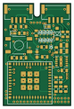
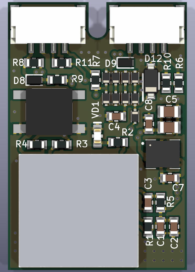
Kogger UART WiFi Bridge is an open source ESP32 PCB design by koggertech, published on GitHub under the MIT license. It is a 4-layer board measuring 20 × 30 mm, with 37 components from 16 distinct parts.
Its main chip is the ESP32-C3-MINI-1U, from the ESP32 family. Other key parts include the LMZM23601V3SILR. By type, the board carries 12 diodes, 11 resistors, 8 capacitors, 2 ICs, 2 crystals and 1 LED.
It belongs with the iot & wireless and usb & debug tools designs in this gallery.
From the project
Open-source ESP32-C3 UART to Wi-Fi bridge: firmware (ESP-IDF), KiCad 10 board, datasheet. Two UART lines relayed to UDP/TCP as whole frames, station or AP with DHCP, control over Kogger SBP, OTA with rollback.
KiCad 10 project of the reference board, the board that was manufactured and is in use. Every drill hole and every solder‑paste opening of this board matches the fabrication files the board was made from (checked, see below).
The outputs are generated by python tools/makehwoutputs.py (needs kicad-cli of KiCad 10).
- Module U1: ESP32‑C3‑MINI‑1U with a U.FL connector for an external 2.4 GHz antenna. The EN pin has a 10 kΩ pull‑up and 1 µF to GND (power‑on delay). The strapping pins GPIO2, GPIO8 and GPIO9 have 10 kΩ pull‑ups. The BOOT button SB1 pulls GPIO9 low. - Power: - VCC arrives on X1…
Main components on the Kogger UART WiFi Bridge
Kogger UART WiFi Bridge bill of materials (BOM)
37 components, 16 distinct parts — part numbers from the project's BOM.
| Qty | Part | Footprint | Refs |
|---|---|---|---|
| 1 | ESP32-C3-MINI-1U Espressif Systems | ESP32-C3-MINI-1U | U1 |
| 1 | LMZM23601V3SILR LMZM23601V3 Texas Instruments | TI_SIL0010A_LMZM2360x | U2 |
| 2 | SM04B-GHS-TB(LF)(SN) SM04B-GHS-TB JST | JST_GH_SM04B-GHS-TB_1x04-1MP_P1.25mm_Horizontal | X1, X2 |
| 1 | PTS525SM15SMTR2 LFS PTS525SM15SMTR2 C&K | SW_CK_PTS525SM15SMTR2 | SB1 |
| 1 | FYLS-0603UGC LED green | LED_0603_1608Metric | VD1 |
| 9 | BAS3005B-02VH6327 BAS3005B-02V Infineon Technologies | D_SC-79 | D1, D3, D4, D6, D7, D10, D11, D13 +1 |
| 2 | SDM4A40EP3-7B SDM4A40EP3 Diodes Incorporated | D_SDM4A40EP3 | D8, D9 |
| 1 | SZMMSZ5226BT1G MMSZ5226B onsemi | D_SOD-123 | D12 |
| 2 | CL10A106MO8NQNC 10uF Samsung Electro-Mechanics | C_0603_1608Metric_Big | C1, C7 |
| 3 | CL10B104JB8NNNC 0.1uF Samsung Electro-Mechanics | C_0603_1608Metric_Big | C2, C4, C8 |
| 1 | CL10A105KB8NNNC 1uF Samsung Electro-Mechanics | C_0603_1608Metric_Big | C3 |
| 2 | CL21A226MAYNNNE 22uF Samsung Electro-Mechanics | C_0805_2012Metric | C5, C6 |
| 4 | ERJ-3EKF1002V 10k Panasonic | R_0603_1608Metric_Big | R1, R3, R4, R5 |
| 3 | ERJ-3EKF1001V 1k Panasonic | R_0603_1608Metric_Big | R2, R10, R11 |
| 2 | ERJ-3EKF1500V 150 Panasonic | R_0603_1608Metric_Big | R6, R7 |
| 2 | ERJ-3GEY0R00V 0 Panasonic | R_0603_1608Metric_Big | R8, R9 |
Kogger UART WiFi Bridge design files
The KiCad project lives in the koggertech/Kogger_UART_WiFi_Bridge repository on GitHub; these links point at the commit this page was built from.
Kogger UART WiFi Bridge: common questions
What microcontroller does the Kogger UART WiFi Bridge use?
The Kogger UART WiFi Bridge is built around the ESP32-C3-MINI-1U, from the ESP32 family.
How big is the Kogger UART WiFi Bridge PCB?
The Kogger UART WiFi Bridge measures 20 × 30 mm, has 4 copper layers and is 1.2 mm thick.
How many components are on the Kogger UART WiFi Bridge?
37 components, from 16 distinct parts, with part numbers taken from the project's own BOM. The full bill of materials is listed on this page.
Where can I download the Kogger UART WiFi Bridge design files?
From the koggertech/Kogger_UART_WiFi_Bridge repository on GitHub, which has the KiCad layout, the schematic and the BOM; the links under Design files point to each one.
Can I use the Kogger UART WiFi Bridge design in my own project?
Yes, under the terms of its MIT license, which koggertech chose for the repository.
Can I test firmware for the Kogger UART WiFi Bridge without the hardware?
Yes. HardLabs builds a simulation of the board from its netlist and BOM, so you can run and debug ESP32 firmware against it before you order a PCB.
Similar boards
 ESP32
ESP32Open Book Abridged Edition
joeycastillo
85 × 115 mm65 parts2LCC-BY-SA-4.08.1k ESP32
ESP32Badge
atopile
56.3 × 39 mm239 parts4LMIT4.0k ESP32
ESP32Esp32 minimal
36.2 × 26.8 mm20 parts2LMIT4.0k ESP32
ESP32Racer
StuckAtPrototype
36 × 50.2 mm70 parts4LApache-2.03.8k ESP32
ESP32Controller
29 × 74 mm58 parts4LApache-2.03.8k ESP32
ESP32Bitaxe
skot
56.5 × 99.8 mm86 parts4LCERN-OHL-S-2.01.4k