
Racer

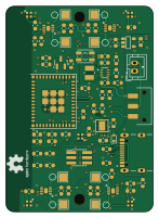
About the Racer PCB
Racer is an open source ESP32 PCB design by StuckAtPrototype, published on GitHub under the Apache-2.0 license. It is a 4-layer board measuring 36 × 50.2 mm, with 70 components from 33 distinct parts.
Its main chip is the ESP32-H2-MINI-1, from the ESP32 family. Other key parts include the A3908EEETR-T, AP2205-33W5-7, MCP73833T-AMI/MF and TPS631000DRLR. By type, the board carries 25 capacitors, 20 resistors, 8 ICs, 5 LEDs, 4 connectors and 3 diodes.
It belongs with the iot & wireless designs in this gallery.
From the project
thank you for the overwhelmingly positve support!! such an inspiration to keep making fun open source content!
thank you for the overwhelmingly positve support!! such an inspiration to keep making fun open source content!
https://github.com/StuckAtPrototype/Thumbtroller
These are structured into their own files. I could have used submodules, but decided against it.
This folder has all the python code you'd need to train up your own neural network for the car. It also consists scripts that let you drive it using a keyboard -- just in case you dont want to make a physical controller.

Main components on the Racer
Racer bill of materials (BOM)
70 components, 33 distinct parts — part numbers from the project's BOM.
| Qty | Part | Footprint | Refs |
|---|---|---|---|
| 4 | A3908EEETR-T A3908 | A3908 | U1, U2, U3, U4 |
| 1 | ESP32-H2-MINI-1 | MODULE_ESP32-H2-MINI-1-H2 | U5 |
| 1 | AP2205-33W5-7 AP2205 | AP2204 | U6 |
| 1 | MCP73833T-AMI/MF MCP73833 | SON50P300X300X100-11N | U7 |
| 1 | TPS631000DRLR | TPS631000DRLR_TEX | U9 |
| 1 | BSS138 | SOT-23 | Q1 |
| 1 | GRPB032VWQS-RC Conn_02x03_SMT | PinHeader_2x03_P1.27mm_Vertical_SMD | J9 |
| 1 | Conn_02x03_SMT | PinHeader_2x03_P1.27mm_Vertical_SMD | J10 |
| 1 | B2B-PH-K-S JST 2.0 BATT | JST_PH_B2B-PH-K_1x02_P2.00mm_Vertical | J12 |
| 1 | USB4105-GF-A USB_C_Plug_USB2.0 | GCT_USB4105-GF-A | P1 |
| 1 | JS102011SAQN | SW_JS102011SAQN | S1 |
| 1 | SWITCH_0SMTRLFS | SWITCH_0SMTRLFS | S2 |
| 1 | NTCG163JF103HT1 TH 10K | R_0603_1608Metric | TH1 |
| 5 | IN-PI15TAT5R5G5B | IN-PI15_INL | LED1, LED2, LED3, LED4, LED5 |
| 1 | TPD1E10B06DYAR TPD1E10B06 | D_SOD-523 | D5 |
| 1 | 150060GS75000 LED_GREEN | C_0603_1608Metric | D8 |
| 1 | 150060RS75000 LED_RED | C_0603_1608Metric | D9 |
| 1 | CIGT252010EH1R0MNE 1uH | RES_CIGT252010 | L1 |
| 9 | GRM188R61A106ME69D 10uF | C_0603_1608Metric | C1, C2, C5, C6, C16, C18, C19, C20 +1 |
| 12 | CC0603KRX7R7BB104 0.1uF | C_0603_1608Metric | C3, C4, C7, C8, C11, C12, C13, C14 +4 |
Show 13 more
| Qty | Part | Footprint | Refs |
|---|---|---|---|
| 1 | GRM188C80E476ME05D 47uF | C_0603_1608Metric | C9 |
| 1 | CC0603KRX5R8BB105 1uF | C_0603_1608Metric | C10 |
| 1 | GRM188R60J226MEA0J 47uF | C_0603_1608Metric | C17 |
| 1 | CL10A225KO8NNNC 10uF | C_0603_1608Metric | C21 |
| 9 | 10K | R_0603_1608Metric | R1, R4, R6, R9, R11, R26, R27, R28 +1 |
| 1 | RQ73C1J806RBTDF 806 | R_0603_1608Metric | R2 |
| 1 | CR0603-FX-91R0ELF 91 | R_0603_1608Metric | R3 |
| 1 | ESR03EZPF4700 470 | R_0603_1608Metric | R5 |
| 1 | RMCF0603FT1M00 1M | R_0603_1608Metric | R16 |
| 3 | RC0603FR-075K1L 5K1 | R_0603_1608Metric | R17, R18, R22 |
| 2 | RC0603JR-07330RL 330 | R_0603_1608Metric | R20, R21 |
| 1 | RT0603BRE071K43L 1.43K | R_0603_1608Metric | R23 |
| 1 | ERJ-PB3B7502V 75K | R_0603_1608Metric | R24 |
Racer design files
The KiCad project lives in the StuckAtPrototype/Racer repository on GitHub; these links point at the commit this page was built from.
Racer: common questions
What microcontroller does the Racer use?
The Racer is built around the ESP32-H2-MINI-1, from the ESP32 family.
How big is the Racer PCB?
The Racer measures 36 × 50.2 mm, has 4 copper layers and is 1.66 mm thick.
How many components are on the Racer?
70 components, from 33 distinct parts, with part numbers taken from the project's own BOM. The full bill of materials is listed on this page.
Where can I download the Racer design files?
From the StuckAtPrototype/Racer repository on GitHub, which has the KiCad layout, the schematic and the BOM; the links under Design files point to each one.
Can I use the Racer design in my own project?
Yes, under the terms of its Apache-2.0 license, which StuckAtPrototype chose for the repository.
Can I test firmware for the Racer without the hardware?
Yes. HardLabs builds a simulation of the board from its netlist and BOM, so you can run and debug ESP32 firmware against it before you order a PCB.
More boards in Racer


Similar boards
 ESP32
OSO-BOOK-B1
joeycastillo
85 × 115 mm65 parts2LCC-BY-SA-4.08.1k ESP32
Powertrain
byrantech
64 × 45.4 mm171 parts4LMIT4.3k ESP32
Esp32 minimal
atopile
36.2 × 26.8 mm20 parts2LMIT4.0k ESP32
Badge
56.3 × 39 mm239 parts4LMIT4.0k ESP32
EinkPDA keyboard
TalismanDesign
95 × 55.5 mm128 parts4LApache-2.02.0k ESP32
Bitaxe
skot
56.5 × 99.8 mm86 parts4LCERN-OHL-S-2.01.4k