
Kitchen timer

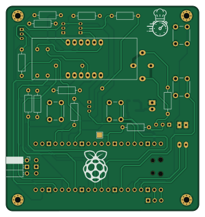
About the Kitchen timer PCB
Kitchen timer is an open source RP2040/RP2350 PCB design by krystofh, published on GitHub under the Apache-2.0 license. It is a 2-layer board measuring 74.2 × 79 mm, with 31 components from 17 distinct parts.
Its main chip is the Pico, from the RP2040/RP2350 family. Other key parts include the 4041BS-1. By type, the board carries 14 resistors, 5 transistors, 5 switches, 3 connectors, 2 ICs and 1 speaker.
It belongs with the displays & leds designs in this gallery.
From the project
TimeUp kitchen timer based on 4-digit segment display, Raspberry Pi Pico and running on Zephyr RTOS
Kitchen timer based on 4-digit 8-segment display 3461BS and RP Pico
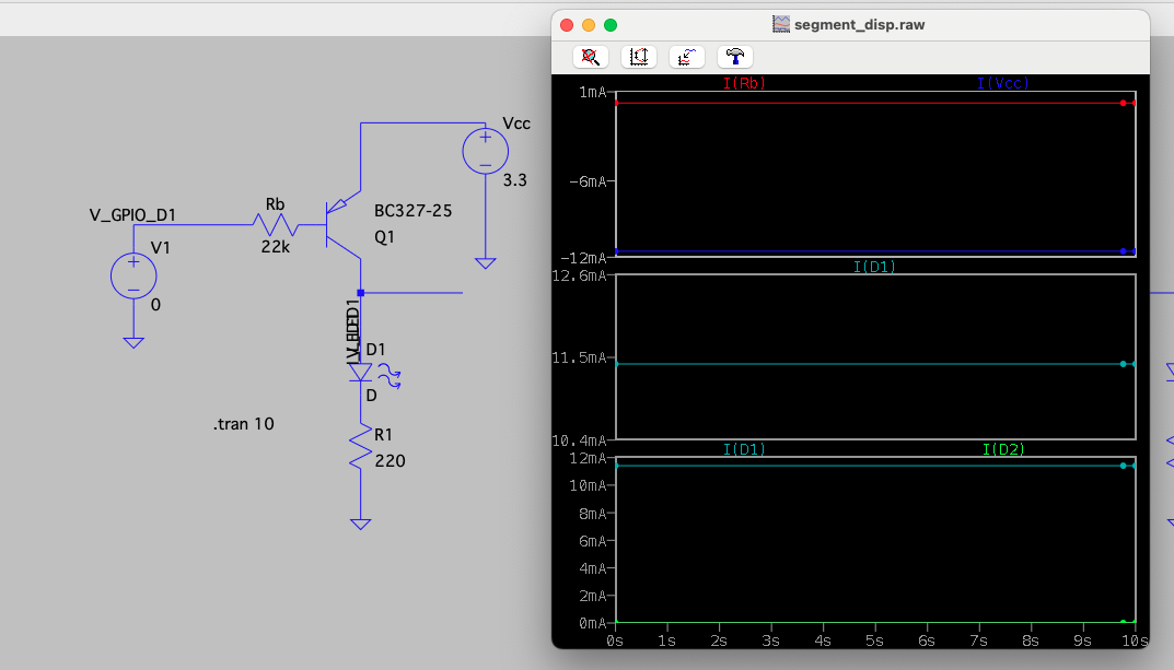
The used display is a common anode display. The datasheet specifies 10 mA typical current for the optical characteristics of a segment. The GPIOs of RP Pico can provide 12 mA max. The built-in 3V3OUT voltage regulator can output up to 300 mA, which is sufficient for all 8 segemts. Not the full 32 segments are needed since the digits are displayed with a given refresh rate sequentially once at a time. Simulation using LTSpice and PNP transistor BCS327-25 leads to the choice of resistor value
Main components on the Kitchen timer
Kitchen timer bill of materials (BOM)
31 components, 17 distinct parts.
| Qty | Part | Footprint | Refs |
|---|---|---|---|
| 1 | 4041BS-1 | Segment_display_4041BS-1 | U1 |
| 1 | Pico | RPi_Pico_SMD_TH | U2 |
| 4 | BC327 | TO-92_Inline | Q1, Q2, Q3, Q4 |
| 1 | BC337 | TO-92L_Inline_Wide | Q5 |
| 1 | JST_2pin_2.5mm | JST_2pin_2.54mm_female | J1 |
| 1 | UART | PinHeader_1x03_P2.54mm_Horizontal | J2 |
| 1 | SWD | PinSocket_1x03_P2.54mm_Horizontal | J3 |
| 1 | Speaker_Crystal | Piezzo_10mm_6.5mm_combined | LS1 |
| 1 | BTN_A | SW_PUSH_6mm_H4.3mm | SW1 |
| 1 | BTN_B | SW_PUSH_6mm_H4.3mm | SW2 |
| 1 | BTN_C | SW_PUSH_6mm_H4.3mm | SW3 |
| 1 | BTN_D | SW_PUSH_6mm_H4.3mm | SW4 |
| 1 | SW_DIP_x02 | DIP-4_W7.62mm_LongPads | SW5 |
| 1 | SEMTECH BAT54S | SOT-23_Handsoldering_renumbered | D1 |
| 8 | 220 | R_Axial_DIN0207_L6.3mm_D2.5mm_P10.16mm_Horizontal | R1, R2, R3, R4, R5, R6, R7, R8 |
| 4 | 22k | R_Axial_DIN0207_L6.3mm_D2.5mm_P10.16mm_Horizontal | R9, R10, R11, R12 |
| 2 | 1k | R_Axial_DIN0207_L6.3mm_D2.5mm_P10.16mm_Horizontal | R13, R14 |
Kitchen timer design files
The KiCad project lives in the krystofh/kitchen_timer repository on GitHub; these links point at the commit this page was built from.
Kitchen timer: common questions
What microcontroller does the Kitchen timer use?
The Kitchen timer is built around the Pico, from the RP2040/RP2350 family.
How big is the Kitchen timer PCB?
The Kitchen timer measures 74.2 × 79 mm, has 2 copper layers and is 1.6 mm thick.
How many components are on the Kitchen timer?
31 components, from 17 distinct parts. The full bill of materials is listed on this page.
Where can I download the Kitchen timer design files?
From the krystofh/kitchen_timer repository on GitHub, which has the KiCad layout and the schematic; the links under Design files point to each one.
Can I use the Kitchen timer design in my own project?
Yes, under the terms of its Apache-2.0 license, which krystofh chose for the repository.
Can I test firmware for the Kitchen timer without the hardware?
Yes. HardLabs builds a simulation of the board from its netlist and BOM, so you can run and debug RP2040/RP2350 firmware against it before you order a PCB.
Similar boards
 RP2040/RP2350
Open Book Abridged Edition
joeycastillo
85 × 115 mm29 parts2LCC-BY-SA-4.08.1k RP2040/RP2350
Corne
foostan
277.2 × 107.5 mm164 parts2LCC-BY-4.07.7k RP2040/RP2350
Corne
277.2 × 107.5 mm164 parts2LCC-BY-4.07.7k RP2040/RP2350
Jitx design
gusmanb
55.5 × 65 mm26 parts4LGPL-3.05.0k RP2040/RP2350
LogicAnalyzer
57 × 55.2 mm6 parts2LGPL-3.05.0k RP2040/RP2350
Main
google
98 × 71 mm102 parts2LApache-2.02.9k