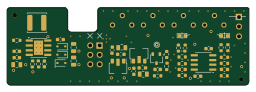
Ksoloti gills

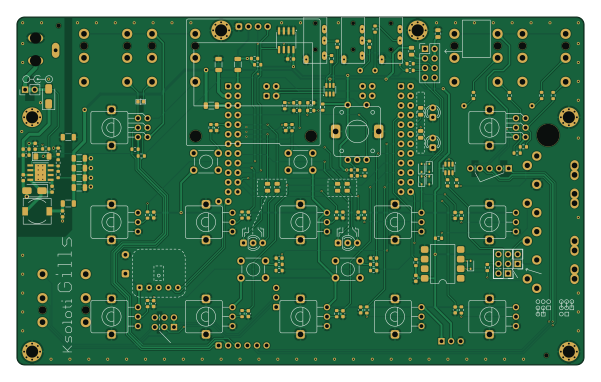
About the Ksoloti gills PCB
Ksoloti gills is an open source PCB design by ksoloti, published on GitHub under the CC-BY-4.0 license. It is a 2-layer board measuring 150 × 92 mm, with 206 components from 58 distinct parts.
Other key parts include the M24512, 74LVC2G17, TPS5430DDA and 6N137. By type, the board carries 53 resistors, 30 capacitors, 20 connectors, 8 diodes, 8 inductors and 5 ICs.
From the project
CAD project and Gerbers for Ksoloti Gills v0.6
Human-readable BOM with notes and links is here
Gerbers for the enclosure panels are in the subfolder /ksoloti-gillspanel/jlcpcb/productionfiles Although the Kicad project includes all panels, there is one gerber zip per panel: top, bottom, left, right, front, rear. If you have made edits and want to update the Gerbers, you will need to create separate Gerbers by pasting each relevant single panel in a temporary PCBNew window and File->Plot... it from there. Or so. Note that there are two ksoloti-gills-panel-top-.zip`, one for black color, one for white. The silkscreens differ.
Main components on the Ksoloti gills
Ksoloti gills bill of materials (BOM)
206 components, 58 distinct parts — part numbers from the project's BOM.
| Qty | Part | Footprint | Refs |
|---|---|---|---|
| 1 | M24512 | SOIC-8_3.9x4.9mm_P1.27mm | U1 |
| 2 | 74LVC2G17 | SOT-23-6 | U2, U9 |
| 1 | TPS5430DDA | TI_SO-PowerPAD-8_ThermalVias | U4 |
| 1 | 6N137 | SMDIP-8_W9.53mm | U5 |
| 1 | Adafruit_PDM_microphone_breakout | Adafruit PDM microphone breakout | M1 |
| 1 | 9-20VDC | dc_socket | J1 |
| 1 | PWR_SWITCH | PinHeader_1x02_P2.54mm_Vertical | J2 |
| 1 | IN_L | Jack_6.35mm_Neutrik_NRJ6HF_Horizontal_no_screwhole | J3 |
| 1 | IN_R | Jack_6.35mm_Neutrik_NRJ6HF_Horizontal_no_screwhole | J4 |
| 1 | OUT_L | Jack_6.35mm_Neutrik_NRJ6HF_Horizontal_no_screwhole | J5 |
| 1 | OUT_R | Jack_6.35mm_Neutrik_NRJ6HF_Horizontal_no_screwhole | J6 |
| 1 | HP_OUT | Jack_6.35mm_Neutrik_NRJ6HF_Horizontal_no_screwhole | J7 |
| 2 | EXP_IO | PJ-320A_THT | J8, J9 |
| 1 | MIDI_OUT | MIDI_DIN-5_DS-5-01c | J10 |
| 1 | MIDI_IO | MIDI_DIN-5_DS-5-01c | J11 |
| 1 | LINE_IN_OUT | PinSocket_1x06_P2.54mm_Vertical | J12 |
| 1 | HP_OUT | PinSocket_1x03_P2.54mm_Vertical | J13 |
| 1 | HP_POT | PinHeader_2x03_P2.54mm_Vertical | J14 |
| 1 | MIDI1_CFG | PinHeader_2x03_P2.54mm_Vertical | J15 |
| 1 | EXPANSION | PinHeader_2x04_P2.54mm_Vertical | J16 |
Show 38 more
| Qty | Part | Footprint | Refs |
|---|---|---|---|
| 1 | GATE_OUT | PJ-320A_THT | J17 |
| 1 | MIDI_OUT_GND | PinHeader_1x02_P2.54mm_Vertical | J18 |
| 1 | OUTPUT_INSERT | PinHeader_1x05_P2.54mm_Vertical | J19 |
| 1 | POWER_HEADER | PinHeader_1x03_P2.54mm_Vertical | J20 |
| 1 | STEC11 | ALPS_STEC12E08 | ENC1 |
| 3 | Conn_01x01_Female | PinSocket_1x01_P2.54mm_Vertical_smcrt_sqr | H1_P1, H2_P1, H3_P1 |
| 53 | Conn_01x01_Female | PinSocket_1x01_P2.54mm_Vertical_smcrt_round | H1_P2, H1_P3, H1_P4, H1_P5, H1_P6, H1_P7, H1_P8, H1_P9 +45 |
| 1 | DMIC_DAT | PinSocket_1x01_P2.54mm_Vertical_smcrt_round | H6_P1 |
| 1 | DMIC_CLK | PinSocket_1x01_P2.54mm_Vertical_smcrt_round | H6_P2 |
| 1 | LR_NORMAL | SolderJumper-2_0603_Bridged_0_25mm | JP2 |
| 10 | B10k | ALPS_POT_VERTICAL_PS | RV1, RV2, RV3, RV4, RV5, RV6, RV7, RV8 +2 |
| 2 | 2*B100k | ALPS_POT_VERTICAL_PS_DUAL | RV11, RV12 |
| 4 | TL1105 | TL1105T | SW1, SW2, SW3, SW4 |
| 1 | GREEN | LED_D3.0mm_marked | LED1 |
| 1 | RED | LED_D3.0mm_marked | LED2 |
| 2 | LED_Dual_AKA | LED_D3.0mm-3_marked | LED3, LED4 |
| 1 | 128x64_OLED | 128x64OLED_1_3in | OLED1 |
| 2 | SS34 | D_SMA | D1, D3 |
| 1 | 3V3 | D_MiniMELF | D2 |
| 1 | 1N4148WS | D_SOD-323 | D4 |
| 4 | 1N5819WS | D_SOD-323 | D5, D6, D7, D8 |
| 5 | 100 ohm @ 100 Mhz | R_1206_3216Metric | FB1, FB2, FB3, FB4, FB5 |
| 2 | 100 ohm @ 100 Mhz | R_0805_2012Metric | FB6, FB7 |
| 1 | 15uh | L_7.3x6.7_H3.5 | L1 |
| 10 | 2.2u | C_0603_1608Metric | C1, C2, C3, C4, C5, C6, C27, C28 +2 |
| 12 | 100n | C_0603_1608Metric | C7, C8, C9, C11, C12, C13, C16, C29 +4 |
| 2 | 10u_25V | C_0603_1608Metric | C10, C41 |
| 1 | 10n | C_0603_1608Metric | C34 |
| 4 | 47u | C_1206_3216Metric | C36, C37, C38, C54 |
| 1 | 2200u 10+V | CP_Radial_D10.0mm_P5.00mm | C53 |
| 17 | 1k | R_0603_1608Metric | R1, R2, R3, R4, R5, R6, R7, R8 +9 |
| 3 | RGREEN | R_0805_2012Metric | R10, R11, R18 |
| 7 | 10k | R_0603_1608Metric | R13, R31, R39, R40, R41, R44, R45 |
| 3 | RRED | R_0805_2012Metric | R14, R32, R38 |
| 15 | 220 | R_0603_1608Metric | R20, R21, R22, R23, R24, R33, R46, R48 +7 |
| 5 | 47k | R_0603_1608Metric | R25, R34, R47, R56, R57 |
| 2 | 2.7k | R_0603_1608Metric | R35, R36 |
| 1 | 3k | R_0603_1608Metric | R49 |
Ksoloti gills design files
The KiCad project lives in the ksoloti/ksoloti-gills repository on GitHub; these links point at the commit this page was built from.
- Layoutksoloti-gills.kicad_pcb
- Schematicksoloti-gills.kicad_sch
- BOMksoloti-gills_v06_bom.xlsx
Ksoloti gills: common questions
How big is the Ksoloti gills PCB?
The Ksoloti gills measures 150 × 92 mm, has 2 copper layers and is 1.6 mm thick.
How many components are on the Ksoloti gills?
206 components, from 58 distinct parts, with part numbers taken from the project's own BOM. The full bill of materials is listed on this page.
Where can I download the Ksoloti gills design files?
From the ksoloti/ksoloti-gills repository on GitHub, which has the KiCad layout, the schematic and the BOM; the links under Design files point to each one.
Can I use the Ksoloti gills design in my own project?
Yes, under the terms of its CC-BY-4.0 license, which ksoloti chose for the repository.