
Rover PCB v2

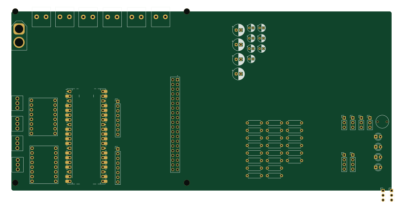
About the Rover PCB v2
Rover PCB v2 is an open source RP2040/RP2350 PCB design by kwag1227, published on GitHub. It is a 2-layer board measuring 203.9 × 96.2 mm, with 62 components from 27 distinct parts.
Its main chip is the RaspberryPi_Pico, from the RP2040/RP2350 family. By type, the board carries 17 connectors, 16 resistors, 10 capacitors, 4 diodes, 1 module and 1 fuse.
It belongs with the sensors and robotics & motion designs in this gallery.
From the project
Stores all files relating to my all-terrain, Perseverance-inspired mars rover.
This repository contains all design files, software, and documentation for an all-terrain, six-legged rover capable of navigating rough terrain and collecting environmental samples. It is a personal robotics project focused on demonstrating skills in embedded systems, motor control, and computer vision.
- Navigate difficult terrain using a rocker-bogie suspension system - Collect and store small samples (e.g., rocks or soil) - Avoid untraversable obstacles using sensors - Showcase design and control of a multi-motor robotic system - Build a custom PCB - Implement ROS2 and Gazebo Simulation
Main components on the Rover PCB v2
Rover PCB v2 bill of materials (BOM)
62 components, 27 distinct parts.
| Qty | Part | Footprint | Refs |
|---|---|---|---|
| 1 | RaspberryPi_Pico | RaspberryPi_Pico_Common_Unspecified | A1 |
| 1 | To_6VA_Converter | 12AWG Screw Terminal | J1 |
| 1 | To_6VB_Convertor | 12AWG Screw Terminal | J2 |
| 1 | Magnetometer_Module_Header | PinHeader_1x04_P2.54mm_Vertical | J3 |
| 1 | IMU_Module_Header | PinHeader_1x08_P2.54mm_Vertical | J4 |
| 1 | GPS_Module_Header | PinHeader_1x05_P2.54mm_Vertical | J5 |
| 1 | Ultrasonic_Sensor_Header | PinHeader_1x04_P2.54mm_Vertical | J6 |
| 1 | 5V_Regulator_Header | PinHeader_1x05_P2.54mm_Vertical | J7 |
| 1 | Raspberry_Pi_4 | SULLINS_PPTC202LFBN-RC | J8 |
| 1 | Servo_PWM_Header | PinHeader_1x08_P2.54mm_Vertical | J9 |
| 4 | Encoder_Header | PinHeader_1x03_P2.54mm_Vertical | J10, J11, J12, J13 |
| 1 | 6VA_In_Screw | 12AWG Screw Terminal | J14 |
| 1 | 6VA_Out_Screw | 12AWG Screw Terminal | J15 |
| 1 | 6VB_In_Screw | 12AWG Screw Terminal | J16 |
| 1 | 6VB_Out_Screw | 12AWG Screw Terminal | J17 |
| 6 | R_US | R_Axial_DIN0207_L6.3mm_D2.5mm_P7.62mm_Horizontal | 10k1, 33k1, 150ohm1, 180ohm1, 180ohm2, 510ohm1 |
| 1 | C | CP_Radial_D4.0mm_P2.00mm | 330uF1 |
| 3 | BDC_Motor_Screw_Terminal | 01x03_Screw_Terminal | BDC_Out_Screw2, BDC_Out_Screw3, BDC_Out_Screw4 |
| 2 | ~ | Motor Driver Board | Driver_Board1, Driver_Board2 |
| 1 | Fuse | Fuse_TH_5A | F1 |
Show 7 more
| Qty | Part | Footprint | Refs |
|---|---|---|---|
| 1 | XT60_Port | AMASS_XT60-F_1x02_P7.20mm_Vertical | XT60 |
| 4 | LED | LED_D3.0mm | D1, D2, D3, D4 |
| 4 | 0.1uF | CP_Radial_D4.0mm_P2.00mm | C1, C4, C6, C9 |
| 4 | 220uF | CP_Radial_D6.3mm_P2.50mm | C2, C3, C5, C10 |
| 2 | 10uF | CP_Radial_D4.0mm_P2.00mm | C7, C8 |
| 8 | 2k | R_Axial_DIN0207_L6.3mm_D2.5mm_P7.62mm_Horizontal | R1, R2, R3, R4, R5, R6, R7, R8 |
| 8 | 1k | R_Axial_DIN0207_L6.3mm_D2.5mm_P7.62mm_Horizontal | R9, R10, R11, R12, R13, R14, R15, R16 |
Rover PCB v2 design files
The KiCad project lives in the kwag1227/Autonomous-Rover-Project repository on GitHub; these links point at the commit this page was built from.
Rover PCB v2: common questions
What microcontroller does the Rover PCB v2 use?
The Rover PCB v2 is built around the RaspberryPi_Pico, from the RP2040/RP2350 family.
How big is the Rover PCB v2?
The Rover PCB v2 measures 203.9 × 96.2 mm, has 2 copper layers and is 1.600198 mm thick.
How many components are on the Rover PCB v2?
62 components, from 27 distinct parts. The full bill of materials is listed on this page.
Where can I download the Rover PCB v2 design files?
From the kwag1227/Autonomous-Rover-Project repository on GitHub, which has the KiCad layout and the schematic; the links under Design files point to each one.
Can I use the Rover PCB v2 design in my own project?
The repository has no license, so all rights stay with kwag1227. Use it as a reference, and ask the author before reusing the design.
Can I test firmware for the Rover PCB v2 without the hardware?
Yes. HardLabs builds a simulation of the board from its netlist and BOM, so you can run and debug RP2040/RP2350 firmware against it before you order a PCB.
More boards in Autonomous-Rover-Project
Similar boards
 RP2040/RP2350
Open Book Abridged Edition
joeycastillo
85 × 115 mm29 parts2LCC-BY-SA-4.08.1k RP2040/RP2350
Corne
foostan
277.2 × 107.5 mm164 parts2LCC-BY-4.07.7k RP2040/RP2350
Corne
277.2 × 107.5 mm164 parts2LCC-BY-4.07.7k RP2040/RP2350
LogicAnalyzer
gusmanb
57 × 55.2 mm6 parts2LGPL-3.05.0k RP2040/RP2350
Jitx design
55.5 × 65 mm26 parts4LGPL-3.05.0k RP2040/RP2350
Pro V2
kata0510
290.1 × 130 mm270 parts2LMIT2.3k