
G474 Integrated Analyzer

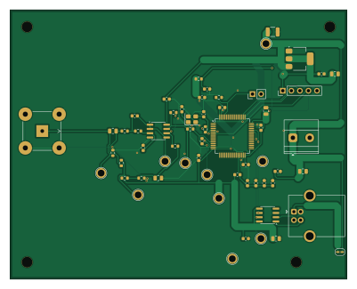
About the G474 Integrated Analyzer PCB
G474 Integrated Analyzer is an open source STM32 PCB design by Larryhul, published on GitHub under the MIT license. It is a 2-layer board measuring 100 × 80 mm, with 49 components from 34 distinct parts.
Its main chip is the STM32G474RBT6, from the STM32 family. Other key parts include the OPA2365AIDR, CH340N and AMS1117-3.3. By type, the board carries 26 capacitors, 12 resistors, 4 ICs, 4 connectors, 1 crystal and 1 jumper.
It belongs with the test & measurement designs in this gallery.
From the project
STM32G474 periodic signal analyzer: FFT harmonic measurement (Upp/Urms/fundamental/spectrum), OPA2365 front end, KiCad PCB, firmware & dashboard. 2026 Shanghai electronic design contest, Problem G. 周期信号测量分析装置
本目录用于老师要求的后续集成任务,不替代已经提交的电赛作品。目标是把实测通过的单片OPA2365二阶前端、NUCLEO-G474RE主控功能、FFT算法和USB串口通信集成到一块新PCB。新板不接DGUS显示屏,电脑上位机负责显示Upp、Urms、基频、各频率分量峰值、1/3周期波形和离散频谱。
- 建立独立固件副本,原实测通过目录未修改。 - 算法、采样、标定和波形文件与实测版本SHA256一致。 - 删除集成版DGUS源文件和运行调用。 - USART1(PA9发送、PA10接收)作为专用ASCII上位机链路,经CH340N接电脑,115200 8N1。 - Release编译通过并生成ELF、HEX、BIN和MAP文件。 - 上位机改为优先自动识别CH340串口。 - 完成主控引脚表、关键网络表、集成BOM、设计说明和首板验收清单。
Main components on the G474 Integrated Analyzer
G474 Integrated Analyzer bill of materials (BOM)
49 components, 34 distinct parts — part numbers from the project's BOM.
| Qty | Part | Footprint | Refs |
|---|---|---|---|
| 1 | OPA2365AIDR | SOIC-8_3.9x4.9mm_P1.27mm | U1 |
| 1 | STM32G474RBT6 | LQFP-64_10x10mm_P0.5mm | U2 |
| 1 | CH340N | SOIC-8_3.9x4.9mm_P1.27mm | U3 |
| 1 | AMS1117-3.3 | SOT-223-3_TabPin2 | U4 |
| 1 | 24MHz CL=8pF | Crystal_SMD_3225-4Pin_3.2x2.5mm | Y1 |
| 1 | BNC INPUT | BNC_TEConnectivity_1478035_Horizontal | J1 |
| 1 | USB_B | USB_B_OST_USB-B1HSxx_Horizontal | J2 |
| 1 | EXT 5V INPUT | TerminalBlock_Phoenix_MKDS-1,5-2_1x02_P5.00mm_Horizontal | J3 |
| 1 | SWD | PinHeader_1x05_P2.54mm_Vertical | J4 |
| 1 | BOOT0 HIGH | PinHeader_1x02_P2.54mm_Vertical | JP1 |
| 1 | 600R@100MHz | L_0603_1608Metric | FB1 |
| 1 | 100nF C0G | C_0805_2012Metric | C1 |
| 1 | 470nF | C_0805_2012Metric | C2 |
| 1 | 150pF C0G | C_0603_1608Metric | C3 |
| 1 | 68pF C0G | C_0603_1608Metric | C4 |
| 1 | 100pF C0G | C_0603_1608Metric | C5 |
| 9 | 100nF | C_0603_1608Metric | C6, C7, C8, C9, C10, C18, C20, C22 +1 |
| 2 | 4.7uF | C_0805_2012Metric | C11, C23 |
| 1 | 1uF VDDA | C_0603_1608Metric | C12 |
| 1 | 10nF VDDA | C_0603_1608Metric | C13 |
Show 14 more
| Qty | Part | Footprint | Refs |
|---|---|---|---|
| 1 | 1uF VREF | C_0603_1608Metric | C14 |
| 1 | 100nF VREF | C_0603_1608Metric | C15 |
| 1 | 100nF VBAT | C_0603_1608Metric | C16 |
| 2 | 10uF | C_0805_2012Metric | C17, C19 |
| 1 | 47uF LOW ESR | C_1210_3225Metric | C21 |
| 2 | 12pF C0G | C_0603_1608Metric | C25, C26 |
| 1 | 51R 1% | R_0603_1608Metric | R1 |
| 1 | 10k 1% | R_0603_1608Metric | R2 |
| 2 | 1.8k 1% | R_0603_1608Metric | R3, R4 |
| 1 | 39k 0.1% | R_0603_1608Metric | R5 |
| 3 | 10k 0.1% | R_0603_1608Metric | R6, R7, R8 |
| 1 | 47R 1% | R_0603_1608Metric | R9 |
| 2 | 10k | R_0603_1608Metric | R10, R11 |
| 1 | 0R | R_0603_1608Metric | R14 |
G474 Integrated Analyzer design files
The KiCad project lives in the Larryhul/periodic-signal-analyzer repository on GitHub; these links point at the commit this page was built from.
- Layout03_申优_电赛G题/07_集成芯片版/hardware/KiCad_G474_Integrated/DELIVERY_20260811_改进版/G474_Integrated_Analyzer.kicad_pcb
- Schematic03_申优_电赛G题/07_集成芯片版/hardware/KiCad_G474_Integrated/DELIVERY_20260811_改进版/G474_Integrated_Analyzer.kicad_sch
- BOM03_申优_电赛G题/07_集成芯片版/hardware/KiCad_G474_Integrated/DELIVERY_20260811_改进版/G474_Integrated_Analyzer_BOM.csv
G474 Integrated Analyzer: common questions
What microcontroller does the G474 Integrated Analyzer use?
The G474 Integrated Analyzer is built around the STM32G474RBT6, from the STM32 family.
How big is the G474 Integrated Analyzer PCB?
The G474 Integrated Analyzer measures 100 × 80 mm, has 2 copper layers and is 1.6 mm thick.
How many components are on the G474 Integrated Analyzer?
49 components, from 34 distinct parts, with part numbers taken from the project's own BOM. The full bill of materials is listed on this page.
Where can I download the G474 Integrated Analyzer design files?
From the Larryhul/periodic-signal-analyzer repository on GitHub, which has the KiCad layout, the schematic and the BOM; the links under Design files point to each one.
Can I use the G474 Integrated Analyzer design in my own project?
Yes, under the terms of its MIT license, which Larryhul chose for the repository.
Can I test firmware for the G474 Integrated Analyzer without the hardware?
Yes. HardLabs builds a simulation of the board from its netlist and BOM, so you can run and debug STM32 firmware against it before you order a PCB.
More boards in periodic-signal-analyzer
Similar boards
 STM32
LumenPnP Motherboard
opulo-inc
149 × 95 mm296 parts4LCC-BY-SA-4.03.7k STM32
Type g
google
169 × 30 mm24 parts2LApache-2.02.9k STM32
Main panel
234 × 84 mm26 parts4LApache-2.02.9k STM32
Base
52.3 × 52.3 mm36 parts2LApache-2.02.9k STM32
Type a
150 × 30 mm14 parts2LApache-2.02.9k STM32
Type c
188 × 30 mm17 parts2LApache-2.02.9k