
DataAcq-Leaderboard

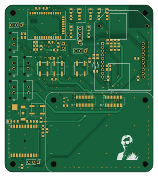
About the DataAcq-Leaderboard PCB
DataAcq-Leaderboard is an open source PCB design by lhr-solar, published on GitHub. It is a 2-layer board measuring 80 × 90 mm, with 76 components from 40 distinct parts.
Other key parts include the PA1616S. By type, the board carries 27 resistors, 18 capacitors, 12 connectors, 8 diodes, 4 switches and 2 transistors.
It belongs with the rf & radio, iot & wireless and power & battery designs in this gallery.
From the project
This PCB is designed for our solar vehicle to collect electrical and mechanical sensor data and transmit it wirelessly via LTE for real-time access. It also includes a GPS module for location tracking and an RF module as a backup communication system.
This PCB is designed for our solar vehicle to collect electrical and mechanical sensor data and transmit it wirelessly via LTE for real-time access. It also includes a GPS module for location tracking and an RF module as a backup communication system.
HB (D7): Heartbeat. Blinking = Our code is running on module. RSSI (D5): Received Singal Strength Integrity. PWM based on strength (brighter = better). CONN (D4): Connection Indicator. On, solid = Not connected. 1/2 sec period blink = Last transmit failed. 1 sec blink period = Normal operation. ON (D6): On. On = Module is on.
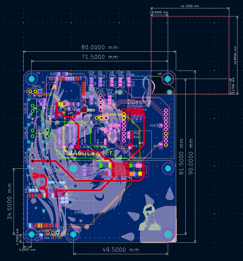
Main components on the DataAcq-Leaderboard
DataAcq-Leaderboard bill of materials (BOM)
76 components, 40 distinct parts — part numbers from the project's BOM.
| Qty | Part | Footprint | Refs |
|---|---|---|---|
| 1 | PA1616S PA1616S_GPS | PA1616S_ADA | U1 |
| 2 | IRLML0030TRPBF NMOS | SOT-23-3 | Q1, Q2 |
| 1 | XB-9XR-DMRM-001 DigiXBeeRX900Micro | XBeeXR900RFMicro | X1 |
| 1 | XB3-C-G4-UT-001 DigiXBee3LTECat4 | DigiXBee3LTECat4 | X2 |
| 1 | 22-28-4035 RF_UART | PinHeader_1x03_P2.54mm_Vertical | J1 |
| 1 | 53307-2471 ~ | LeaderSOM | J2 |
| 1 | 22-28-4028 SOM_POWER | PinHeader_1x02_P2.54mm_Vertical | J3 |
| 1 | 43650-0215 PWR_OUT | CONN_SD-43650-006_02_MOL | J4 |
| 1 | 43650-0215 ICAN_IN | CONN_SD-43650-006_02_MOL | J5 |
| 1 | 43650-0215 CCAN_IN | CONN_SD-43650-006_02_MOL | J6 |
| 1 | 43650-0215 CCAN_OUT | CONN_SD-43650-006_02_MOL | J7 |
| 1 | 43650-0215 PWR_IN | CONN_SD-43650-006_02_MOL | J8 |
| 1 | 22-28-4035 LTE_UART | PinHeader_1x03_P2.54mm_Vertical | J9 |
| 1 | 22-28-4045 LTE_Trace | PinHeader_1x04_P2.54mm_Vertical | J10 |
| 1 | 22-28-4035 GPS_I2C | PinHeader_1x03_P2.54mm_Vertical | J11 |
| 1 | GPS_BAT | TestPoint_HEX_3mmID | J12 |
| 1 | 2994TR ML414 | BAT_2994TR | BAT1 |
| 1 | B3SL-1002P RF_RESET | SW_SPST_B3SL-1002P | SW1 |
| 1 | B3SL-1002P RF_COM | SW_SPST_B3SL-1002P | SW2 |
| 1 | B3SL-1002P LTE_RESET | SW_SPST_B3SL-1002P | SW3 |
Show 20 more
| Qty | Part | Footprint | Refs |
|---|---|---|---|
| 1 | B3SL-1002P GPS_RESET | SW_SPST_B3SL-1002P | SW4 |
| 1 | APTD2012LCGCK RF_COM_LED | LED_0805_2012Metric | D1 |
| 1 | APTD2012LCGCK RF_ON | LED_0805_2012Metric | D2 |
| 1 | APTD2012LCGCK RF_RSSI | LED_0805_2012Metric | D3 |
| 1 | APTD2012LCGCK LTE_CONN | LED_0805_2012Metric | D4 |
| 1 | APTD2012LCGCK LTE_RSSI | LED_0805_2012Metric | D5 |
| 1 | APTD2012LCGCK LTE_ON | LED_0805_2012Metric | D6 |
| 1 | APTD2012LCGCK LTE_HeartBeat | LED_0805_2012Metric | D7 |
| 1 | APTD2012LCGCK !3D_FX | LED_0805_2012Metric | D8 |
| 1 | BLM15BD601SN1D FerriteBead | R_0402_1005Metric | FB1 |
| 2 | TCP0J106M8R 10u | C_0805_2012Metric | C1, C9 |
| 7 | C0805C105J4RAC7210 1u | C_0805_2012Metric | C2, C4, C5, C14, C15, C17, C18 |
| 1 | C0805C470F5GACTU 47p | C_0805_2012Metric | C3 |
| 3 | TCTPL0G107M8R-V1 100u | C_0805_2012Metric | C6, C7, C8 |
| 2 | C0805C103F8HACAUTO 10n | C_0805_2012Metric | C10, C13 |
| 1 | C0805C560FBGACTU 56p | C_0805_2012Metric | C11 |
| 1 | C0805C100F1GACTU 10p | C_0805_2012Metric | C12 |
| 1 | C0805C104M5RACTU 100n | C_0805_2012Metric | C16 |
| 15 | CRCW080510K0FKEA 10k | R_0805_2012Metric | R1, R2, R3, R4, R5, R7, R12, R15 +7 |
| 12 | CRCW08051K00FKEAC 1k | R_0805_2012Metric | R6, R8, R9, R10, R11, R13, R14, R21 +4 |
DataAcq-Leaderboard design files
The KiCad project lives in the lhr-solar/DataAcq-Leaderboard repository on GitHub; these links point at the commit this page was built from.
DataAcq-Leaderboard: common questions
How big is the DataAcq-Leaderboard PCB?
The DataAcq-Leaderboard measures 80 × 90 mm, has 2 copper layers and is 1.6 mm thick.
How many components are on the DataAcq-Leaderboard?
76 components, from 40 distinct parts, with part numbers taken from the project's own BOM. The full bill of materials is listed on this page.
Where can I download the DataAcq-Leaderboard design files?
From the lhr-solar/DataAcq-Leaderboard repository on GitHub, which has the KiCad layout, the schematic and the BOM; the links under Design files point to each one.
Can I use the DataAcq-Leaderboard design in my own project?
The repository has no license, so all rights stay with lhr-solar. Use it as a reference, and ask the author before reusing the design.
Similar boards

Stack chan
stack-chan
50 × 50 mm33 parts2LApache-2.01.7k
Display Carrier
AxxAxx
35.6 × 58.2 mm5 parts2LGPL-3.01.7k
ControllerCurrentShuntAddOn
stuartpittaway
26 × 16.9 mm9 parts2LCC-BY-NC-4.01.1k
Module 16S PassiveBalanceAddOn
61 × 74 mm86 parts2LCC-BY-NC-4.01.1k
TemperaturePCB PANEL
116 × 75.5 mm178 parts2LCC-BY-NC-4.01.1k
ProgrammingAdapter
10.5 × 83 mm3 parts2LCC-BY-NC-4.01.1k